Why should you create an electronic circuit?
My daughter has asked me: “What is an electronic circuit?” It is a combination of electronic components in a specific way. Whereby we connect it with the conductor wires for the electrical current to flow through.
Answered: It is a great activity for learning and hobbies.
What electronic circuit should we create?
Also, I have been teaching my children how to learn electronics for beginners. But, they sort of do not understand the theory. It is complicated and boring for the kids to understand. You maybe are like my children.
Ancient people once said that:
I hear and I forget; I see and I remember; I do and I understand.
It is true.
Therefore, I believe that creating an electronic circuit will help us understand it easily.
Here are Simple Electronic Circuits for beginners
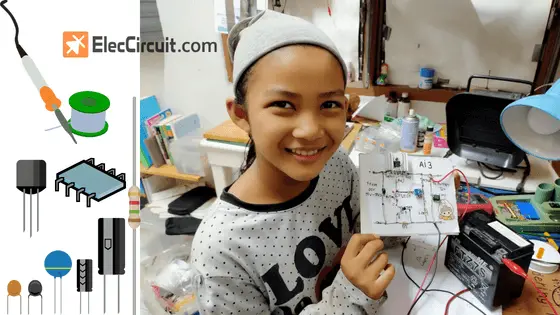
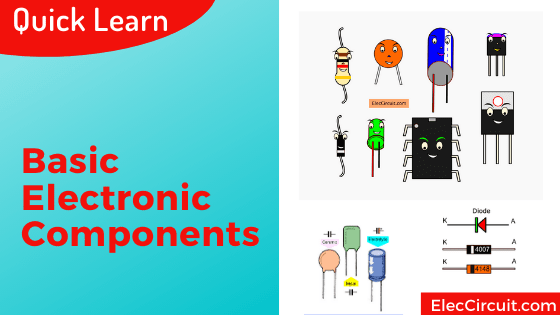
Let me tell you about the basic electronic components list with images. If without knowing the name and how they work, then we cannot use them to build electronic circuits.
Very enjoyable Hobby
If you have free time, Electronics are a good way to spend your free time by creating simple electronic projects to improve your daily life.
But the most important thing does not to regret it whenever your projects have failed. It is your learning process.
10 recommended Electronic circuit
- Automatic Solar Light circuit
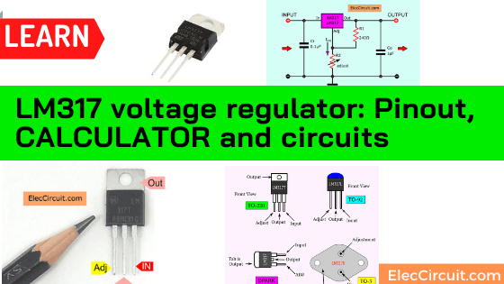
- LM317 Power supply The first power supply that I created!
- 0-30v 3A power supply: Use this for most projects. It is an easy and new design
- 0-50V, 3A variable supply
- Inverter circuit
- Simple Li-ion Battery Charger Circuit with Automatic Cut-Off
- MOSFET Amplifier circuits
- Preamplifier with Tone control
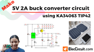
- 12V to 5V DC converter circuit. See many simple ways to get 5V from a 12V source you will choose the best choice for your work.
What is more? Look:
Interested Components
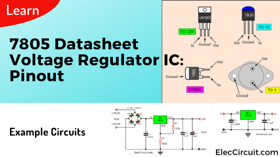
7805 regulators Most popular ICs for 5Vpower supply.
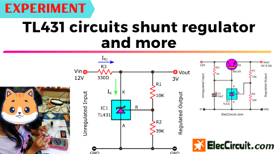
Experiment Electronics
Last Updated Circuits
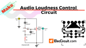
Audio Loudness control
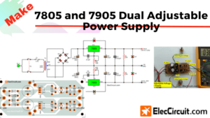
7805 and 7905 Dual adjustable power supply project
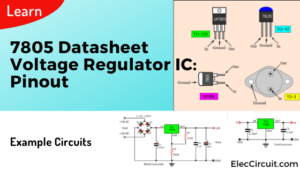
7805 datasheet voltage regulator IC: Pinout and example circuits
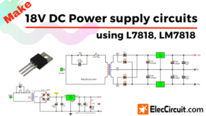
18V DC power supply circuit using LM7818
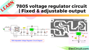
7805 voltage regulator circuit | Fixed & adjustable output
Creating Transistor Series Voltage Regulator circuit