Today, let’s try to use a transistor as a switch. My daughter asked me why I was using transistors. Answering this question might be best if we were to carry out real experimentation, and better learn and understand first-hand.
Our goal in this article is to learn how to use a transistor at its basic level, using it as a switch.
Thus, we would not introduce you to some other, more complex principles or theories because it isn’t very suitable for my daughter right now.
Anyhow, I hope these will be of great use to you one way or another.
Preparing equipments
In this experiment, we are going to pick up most of the components already in our storage. which are: a 12V, 3Ah battery, and a light bulb.
We use light bulbs that have been used in old motorcycles. Although it is quite ancient by now, it emits a faint light and uses a high amount of energy. It can help us learn about electrical current and visualise any change easily.
In this experiment, we are not going to use a breadboard; instead, we are going to build our own testing board.
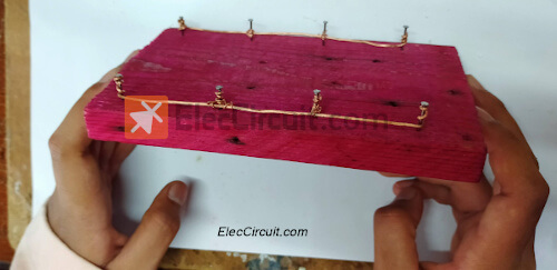
The testing board is very easy to build. made from small wooden planks (around 10cm by 15 cm), nail in a few nails, and wire it with copper 1mm wire to it.
We soldered each nail together with the said copper wire into a simple circuit. Therefore, we can take or measure electricity at each point easily. This type of board is suitable for circuits with few details.
Basic electronic circuit
The simplest circuit to experiment with is connecting a light bulb to the battery. But it is quite bothersome to turn the light bulb on or off. So we add in the push-bottom switch as shown below.
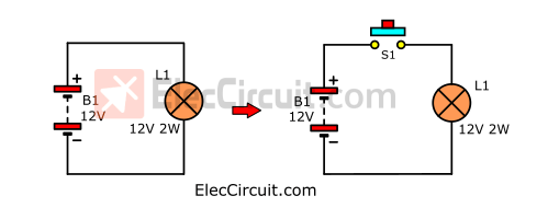
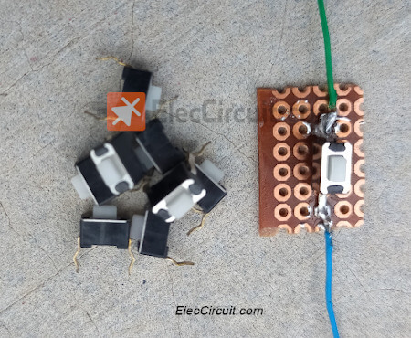
We prefer a Micro switch because it is quite cheap and can be soldered or plugged into a breadboard very easily.
According to the datasheet, it can push more than 100,000 times, making it suitable for mouse buttons.
But there is still a bottleneck, which is that its rated load is DC12V 0.1A.
If used with a 12V 10W light bulb, it would have a current of around 0.7A. seven times more than what the switches could handle, and it can be damaged.
We would need to use a transistor to handle that high current instead. so that we can still use this exact same Microswitch.
Note: In the picture above, we soldered this Mico switch onto the Perforated Circuit Board and wired a connector so that it would be more convenient to use.
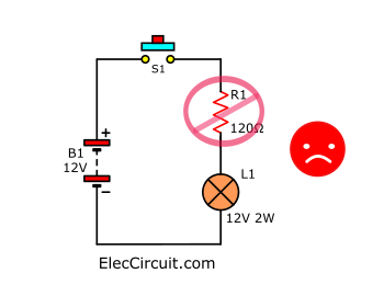
Could we reduce the current with a resistor instead?
My daughter asked: Can we reduce the current through S1 with a resistor? But when the current through L1 decreases, it also reduces the brightness of the light bulbs, which we don’t want.
Let’s experiment with a transistor as a switch
As we already know, the transistor is a semiconductor, making it functional as a switch as well. It’s still being widely used, even though we already have IC.
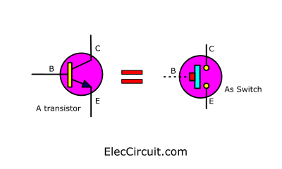
The transistor has a very similar characteristic to a push-button switch. But instead of pushing it, we apply a small current to B, and it will let through a bigger current to flow from C to E.
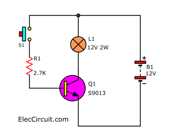
Start the first transistor switch circuit
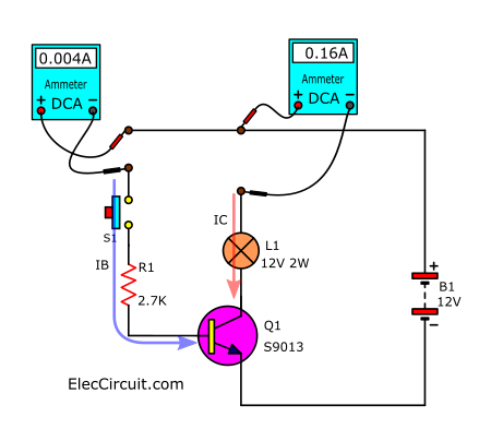
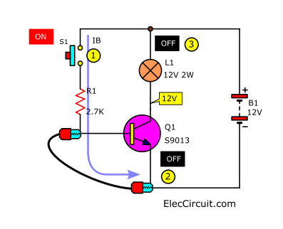
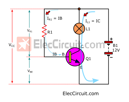
First, let’s assemble the first circuit according to the circuit below.
After we are done assembling the circuit, let’s start the experimentation.
1. Measure the voltage of the battery (Vbat); the result we got is around 12.49V.
2. Measure the voltage at the C and E pins of Q1 (VCE) or GND. What we got is around 12.45V because current can flow through L1 to the meter’s measurement point. The transistor is in a cut-off state.
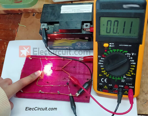
3. Push the switch S1, and we will see the light bulb (load of the circuit) light up immediately. The voltage at C drops down to about 0.11V. This shows that the transistor Q1 works in the same vein as the On switch (closed), and the voltage drop across it is very low to the point of almost zero.
4. Measure the voltage at B and E of Q1 (VBE); currently, it is 0.7V.
5. Disconnect one lead of the L1 and measure the current flowing through it (load current). It is exactly the same as the one flowing through the C pin of the transistor. We call this current an ‘IC’ (collector current), and it has values around 0.16A; normally, the light bulb uses about 0.17A of current.
From the result we got, it shows us that the resistor can turn On or Off electricity with the same efficiency as other common switches.
6. Measure the current that flows through R1, which is the same current that flows through pin B of Q1 and S1; currently, it is around 0.004A.
The result we got from measuring the IB shows us that the current flows through the switch are very small and definitely within the specs the manufacturer stated.
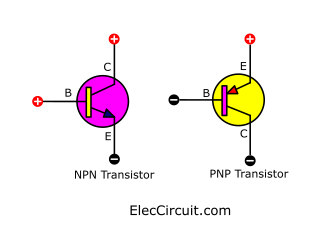
Polarity of the transistor
We try switching the transistor’s C-E legs, as shown below.
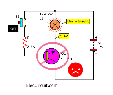
But when we apply the power, the light bulb lights up faintly, even though we haven’t pressed switch S1. and the Q1 also starts to heat up because the Q1 has received a reversed bias.
Both NPN and PNP transistors will not work unless it’s connected in a proper polarity.
Why put in R1?
My daughter asked me: What would happen if we didn’t add R1 (RB)? So we try using double-end alligator clip wire to short-circuit across R1 and simulating what happens when there is no R1 but instead a simple wire from S1 and B of Q1.
The clip heads are called alligator clips, so I’m going to call the wires alligator wires. It’s okay if your wires are longer, but they may get more tangled.
Then press the S1 again. But now the light bulb lights up just for a few seconds, and there is smoke coming out of the transistor. Because pin B cannot handle current higher than what it’s rated for.
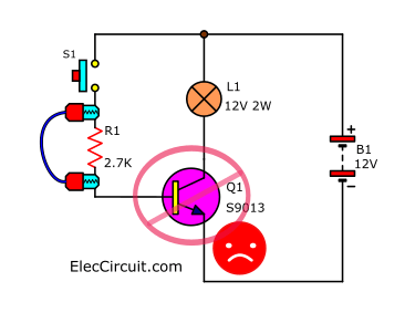
So it got damaged immediately.
Then what is the maximum voltage and current for the base of the transistor?
This is answered in the manufacturer’s datasheet.
In there, we see that S9013 can receive VBE at most 5V, thus getting damaged when instead it receives 12V.
The next question is: What voltage is suitable for them in their switch mode? The awnser is around 0.6V to 0.9V.
How do you stop a transistor from working?
So we know how to turn the transistor on; now let’s see how to turn the transistor off as you could do with a normal switch. It is simple: remove the VBE.
1. Short circuit between B and E
When we continuously press on the S1, L1 lights up. But when we connect the alligator wires between B and E, Q1 will turn off, as will L1. Measuring the voltage at pin C, the reading is 12V because the transistor acts as an open switch.
2. Stop transistor with negative voltage.
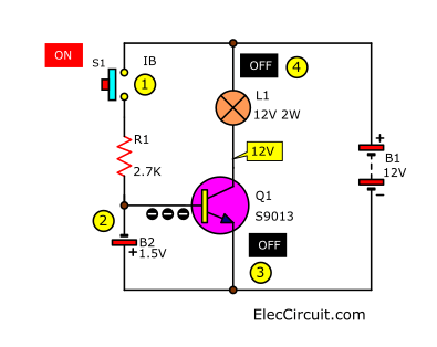
First, press S1. We will see the L1 light up, and then we will connect the 1.5V battery to the Base and Emitter of Q1. causing the L1 to turn off immediately because the transistor stopped working and functioning as an OFF switch. With this method, we can easily make an LED flasher circuit with the use of capacitor charging and discharging to control when the transistor works.
Knowing the necessary specs of the transistor
Let’s see the different important values of the transistors.
NPN Epitaxial Silicon Transistor
Electrical Characteristics
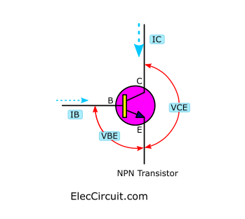
VCE: Collector-Emitter Voltage
VBE: Base-Emitter Voltage
IC: Collector Current
IB: Base Current (max)
hFE: DC Current Gain
PC: Colletor Power Dissipation
| Name | VCE(max) | VBE(max) | IC(max) | IB(max) | hFE(min) | PC |
|---|---|---|---|---|---|---|
| S9013 | 20V | 5V | 500mA | 50mA | 60 | 650mW |
| BD139 | 80V | 5V | 1.5A | 0.5A | 25 | 12W |
| TIP41 | 60V | 5V | 6A | 2A | 20 | 65W |
In this experiment, we use three NPN transistors that have different values and shapes. They are: S9013, BD139, and TIP41.
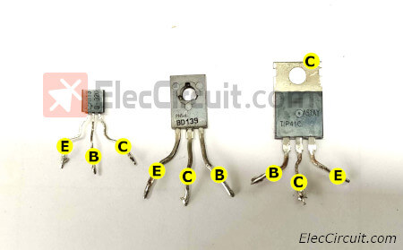
Each transistor has a different pin placement. So be extra careful when using them, because if connected in the wrong way, the circuit might not work and may get damaged.
Finding R1 value easily
Have you wondered why the R1’s value is 2.7K? There is an easy way to find its value, so let’s look into it, shall we?
Start by understanding all related variables first.
According to general principles, the resistance is equal to the voltage drops across it, divided by the current flowing through it.
R1 = VR1/IR1
From the diagram below
VR1 = VCC – VBE
VCC = 12.49V (battery voltage) and VBE = 0.7V
Because transistors normally work in saturation state when VBE is approximately 0.6V to 0.8V.
Therefore, we set VBE to be equal to 0.7V.
Instead of value
VR1 = 12V – 0.7V
VR1 = 11.3V
As IR1 is the same current as IB, we will consider IB instead. The transistor amplifies the current IB into an IC. The ratio of this amplification is hFE. It can be concluded into a simple formula as follows:
IB = IC/hFE
IC is the current that flows through the load, or the light bulb in this case. We use a 12V 2W light bulb.
From the standard formula I = P/V
Given that P = 2W and V = 12V
Substitute
I = 2W/12V
I = 0.17A
Therefore, the IC is approximately 0.17A, consistent with the experimental results above.
As for hFE, we can usually see it in the datasheet. It has the lowest value, which is 60.
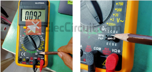
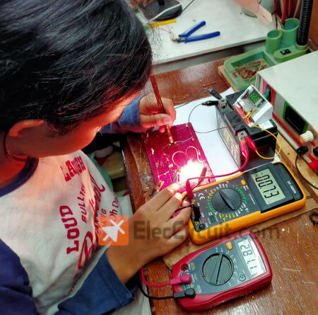
Find the hFE value with a meter
We can also measure the hFE of the transistor. By inserting its legs into the sockets of the meter in the leg type, for example, S9013 or C9013 is of the NPN type.
Buy these transistors at Amazon.com here (Affiliated link)
We measured 92, as shown in the picture below.
But when using it in a calculation, we might want to use the lower 60 value instead. because the hFE value may change according to the electric current.
Then we try to substitute those values into the formula.
IB = 0.17A / 60
IB = 0.0028A
Substitute in the formula above.
R1 = VR1 / IB
R1 = 11.3V / 0.0028A
R1 = 4,035Ω, or the 3.9K resistor that we used
But the IC value is lower than 0.17A, which is about 0.15A. We guess that because the hFE value is low, the solution is to try increasing the IB value and lowering the hFE value by half, which is 45.
We will get
IB = 0.17A / 60
IB = 0.0038A
R1 = 11.3V / 0.0038A
R1 = 2,973Ω, or the 2.7K resistor that we used
And the results are like those above.
Or it may be summarized as a short formula:
R1 = (VCC-VBE) / (IC/hFE)
Try increasing the load size
We wonder what will happen if we increase the load size. by changing it to 12V 10W or around 0.7A of current.
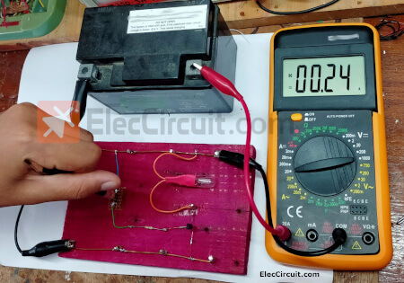
But with the original circuit above, the light bulb turns off completely, and there is only 0.24A of current through the light bulb load. The transistor also gets very hot, but its hull cannot be mounted to the heat sink.
So we changed to a larger transistor, BD139, and according to the table above, it can accept a maximum IC of 1.5A.
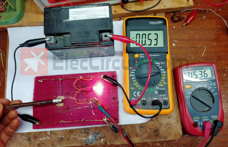
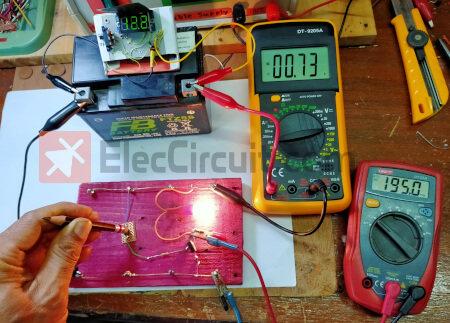
The results show that the light bulb lights up, the current is measured at 0.53A, and the voltage at pin C is measured at 5.36V, showing that the transistor is working. But the current level is still lower than 0.7A, so change R1 to 1K to have more IB.
The results came out as expected. We measured a current of about 0.7A, and the VCE dropped to only about 280mV, or 0.28V. But when touching the BD139, it gets very hot, probably because it can handle no more than 1.5A, but right now it’s handling about 50% of its maximum. Therefore, it generates high heat. We should mount it with the heat sink or change it to a transistor that can withstand a higher current.
So we tried changing the transistor to TIP41. According to the datasheet, it can withstand a maximum current of 6A.
We assembled a new circuit as shown, changed R1 to 330Ω, and the results turned out as good as expected.
TIP41 is just a bit warm to the touch. Because it can withstand a maximum current of 6A or 65W, we use a 10W light bulb at a current of about 0.7A, equivalent to only 10% to 20%. so there is no need to attach a heat sink.
Using a PNP transistor as a switch
Normally, we use NPN transistors about 90% of the time, but sometimes PNP transistors are more suitable to use. For example, in: Simple Automatic Motion Sensor Light Circuit
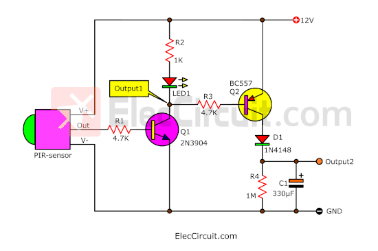
Because we can easily release electricity at the output.
Conclusion
In this experiment with the transistor circuit as a switch, it can answer questions. With real results, it is easier to understand because this is really learning through experience.
- Always choose a transistor with a current rating of more than 50% of the load. For example, if the load uses a current of 1A or 15W, you should use a transistor with an IC value of about 15A or 115W.
- If the transistor or IC is too hot to touch, you should install a heat sink and have a fan blow on it to cool it down. This makes it more efficient.
- Connect the transistor to the correct terminal and always put in RB (R1).
We lost several transistors with this experiment. But it’s worth the value of this experience.
On other occasions, we will experiment with transistor circuits as signal amplifiers. So please stay tuned.
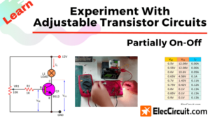
Read next: Experiment with adjustable transistor circuits partially on-off
Download This
All full-size images and PDFs of this post are in this Ebook below. Please support me. 🙂

I love electronics. I have been learning about them through creating simple electronic circuits or small projects. And now I am also having my children do the same. Nevertheless, I hope you found the experiences we shared on this site useful and fulfilling.
thank you
You are welcome.
Hope you will continue to follow us. We will keep the article better. 🙂
Good work. Thank you
Hi,
You’re welcome. Thanks again. 🙂
Hi there
I really liked your explanation through experimentation and appreciate what you are doing for the community. I have a little suggestion for your current article and its that you should explain the PNP transistor working as well or at least similar to the explanation of NPN transistor. It shall complete this article as a whole.
Waiting for your kind response.
Regards
Sam
Hi Sam
First of all, I sincerely thank you, for your advice. It’s true as you said. Even though we use PNP transistors less often, they are still important. And sometimes it is necessary to use it as well. It might help make our work easier.
Next time, I will try it out. And share it with you and other friends as well.
God bless you and your family.
Hi, very good and simple explanation for newcomers to electronics. I am curious what software you use to sketch out those circuit diagrams . They are very colorful and clear. Please share.
Hello, fox,
Thanks for your feedback. I am sorry.
I can’t tell you, because I promised my benefactor. However, it’s just a simple drawing program, not an electronic one.