I am going to show you a small Zener diode voltage regulator circuit with PCB. They use a transistor and Zener diode as main parts.
When I want a fixed DC source circuit or DC voltage regulator, for the normal electronic circuits. For example, preamplifier, digital circuit, etc.
Often I use these simple components in my store. Because they are quick and save money. It is one of the best choices.
Why should we use this circuit
See in the circuit below. Why should we use this circuit?
- The constant output of 12 volts, at a max output current of 1A.
- For the input voltage, you can select both AC (12V to 15V) and DC (15V to 18V)
- It’s flexible. Read more below!
Here are a few related posts you might want to read:
Small Zener diode voltage regulator circuit
Because I like to see you grow up. This circuit came from this.
See: Fixed voltage regulator working principle
How it works
If We need to use a micro preamplifier with a power amplifier. Which it uses a supply 12V 0.5A. We can connect the input terminal to a sec of the transformer.
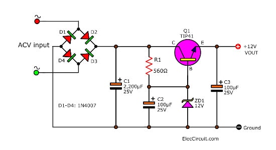
First, the ACV comes to rectifier bridge, D1 through D4, rectifies the AC into pulsating DC.
Second, the capacitor-C1 will smooth that pulsating DC into a steady DC.
Third, this DC flows through resistor-R1 and Zener diodes-ZD1. The R2 reduce a current for ZD1 until it has a constant voltage at VZ, 12V.
Read Also: What is Zener diode? Its principle working and example usage
While there is 12V at the base of transistor-Q1. Since it is in a common collector. So the voltage of base(VB) equals the voltage of emitter(VE).
But while It is conducting, the electrical current flows through B-E. There is the voltage across B-E, 0.6V. Thus, the VE or output voltage is reduced to 11.4V.
When the load makes the output of voltage changes. But the gain of Q1 will make the VE to be the constant voltage.
12V 1A Linear voltage regulator using 2N3055
How to build it
Highlights of this circuit are so small in size. See in below the copper PCB layout. You need to print it in 300dpi per inch. Then, solder the components on PCB as layout below.
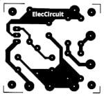
Actual-size of Single-sided Copper PCB layout
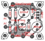
Component layout for the PCB
It is easy, I believe you can do.
Why is it flexible?
Many flexible you should build it.
We can change the output of voltage by ZD1 such as 6V, 9V, 10V. Its power is 1W.
What is least Input voltage? We need to increase input voltage by at least 1.25 times of output. For example, If the output is 15V, The input will equal about DC19V (15V x 1.25) or AC15V.
Important!
We change a voltage of C1 (WVDC) to be 2 times of input. For example, the input is 18V, WVDC should be about 35V. The C1 is 470uF 35V Electrolytic capacitor.
However, we not should use the input voltage more than 25V. Because while the circuit is working will too hot. We cannot use the big heatsink. It is not a small size, it doesn’t our concept at the beginning.
AC transformer
Some friends does not clear about AC in. In these circuits, you can use them 2 form. As the image below. It is different the place of the power switch and fuse. You can use both forms.
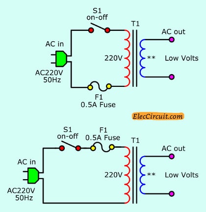
It is important that you have a voltage transformer rating and the output DC voltage.
For example
You need to use 12V 0.5A DC voltage. You should use the secondary coil of the transformer at least 12V. Because when it is converted into DC. The voltage will be about 17V.
From mathematical formulas:
DCV = 1.4V x ACV
For the output current. You should use a transformer at least 0.5A. But 0.75A current is better.
Also, we want you to see the article below they are related.
Bonus:
Zener Diode Dual rail voltage regulator
This is Simple dual rail voltage regulator using zener diode. This is an old circuit that interesting. It is suitable for a low current circuit such as a transistor preamplifier.
The voltages directly available are from a dual-rail +14V/0V/-14V supply at a maximum output current of about 200mA.
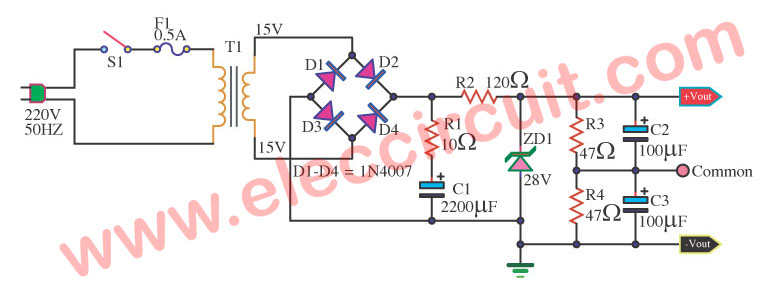
Simple dual-rail voltage regulator using Zener diode circuit diagram
When electrical current flow to the Zener diode in the reverse breakdown voltage. Making the voltage across it is the constant—voltage regulator—to a load.
In the circuit above, it is so easy.
There is an unregulated DC power supply here. They consist of step-down transformer T1, a full-wave rectifier bridge(D1 through D4), and a filtering circuit made up of a capacitor-C1, a resistors-R1.
When 220V/120VAC comes to transformer-T1 through the ON-OFF switch-S1 and Fuse-F1 is a overload protection of circuit. The T1 changes 220VAC to about 30VAC (15V+15V).
Then, the rectifier bridge, D1 through D4, rectifies the AC into pulsating DC.
Next, the capacitor-C1 will smooth that pulsating DC into a steady DC. Which it is the unregulated DC voltage of about 43 volts.
The resistor-R1 connects with C1 together in series. They are a so well low filter.
After that, the DC voltage flows through R2 and ZD1. The resistor-R2 limit current for Zener diodes ZD1 and the load.
Now the voltage(VZ) across ZD1 is the constant voltage of about 28 volts.
Perform maintain one’s position voltage. Be stable and use the principle of divide Voltage. But this voltage still single rail supply.
Next, the two 47 ohms resistors, R2 and R3, it is the easiest way to do this. Dual resistors form a voltage divider. They provide a reference voltage at the output of +14V/0V/-14V.
This circuit is not suitable for a high current load. The output current is less than 200mA.
What is more?
See other circuits use Zener Diode Regulators
- 5V converter circuit using Zener and transistor
- Variable Zener diode circuit
- 5 volts Lab Power supply for beginner
- Power Supply for Audio Amplifier, multiple output 12V, 15V, 35V
Check out these related circuits, too:
Even more importantly. What is better this?
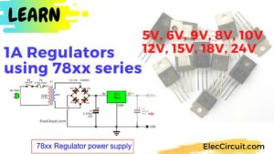
Fixed Regulator Circuits 5V,6V,9V,10V,12V 1A using 78xx series’ »
Related Posts

I love electronics. I have been learning about them through creating simple electronic circuits or small projects. And now I am also having my children do the same. Nevertheless, I hope you found the experiences we shared on this site useful and fulfilling.
By using 2n3055 transistor,how we are getting the increased output?
Hi, dhivya
Thanks for your feedback,.
Yes, it can increase current up.
Hi there,
Do you have a simple circuit for a DC/DC step down 24vdc to 6vdc.. power would be maximum 1 amp.
Many thanks.. great site by the way..
@SMC Just use a 7806 Regulator,,Circuit Diagrams are all over the Internet,,,Google 7806 >>>Good Luck and Good Building!!!!
Hi, MR OHM 1979
Thanks for your helping.
I need simple voltage regulation circuit for 12-V lead acid charging. Rectified input (from PM alternator) is about 40-V open circuit, to be regulated to 13.5-V. 20 amp current capacity would be enough. Where can I find a circuit?