We often use a Zener diode in a lot of electronic circuits. For instance, power supplies, voltage detectors, etc. It is so helpful device in electronics. But…Do you understand well enough?
Today we will learn the Zener diode principle working and example applications usage. Let me explain why we should learn them.
Recommended: For beginners should Learn Electronics.
What is Zener diode
Zener diode is a two-pin device. One type of semiconductor type. That has different properties from a general diode.
Look at the image below, showing the Zener Diode (Right) symbol in an electronic circuit. And the shape of the real one looks like a normal diode (left).
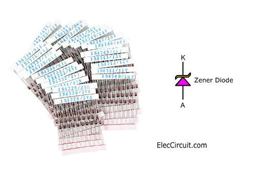
There are many sizes from, according to the wattage. The large size also more watts of power. The picture is only half a watts (1W).
Credit Photo Zener by TeOhk
Basic how Zener diode works
When I was a beginner. I used a long time to understand how it works. You are better than me. I am so happy to see you learn the Zener diode faster.
See a lot of images may help you see.
Look at the block diagram below.
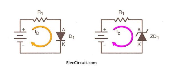
Both Diode and Zener Diodes have different functions and basic bias.
- Left: Rectifier Diode requires a forward bias to work.
- Right: Zener Diode requires a reward bias to work.
What is more?
Internal virtual circuit
Look at the Internal virtual circuit below.
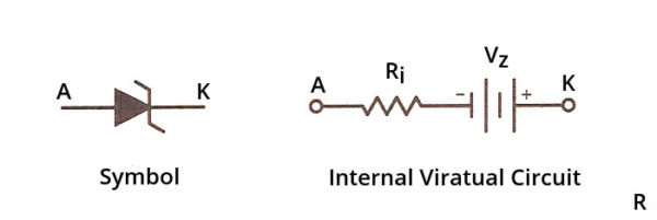
The Zener Diode operates by using breakdown voltage, or Some called Zener diode voltage. When it works during the Reverse bias.
Learn: Relationship Between Current and Voltage
During this breakdown, the voltage drops across the Zener Diode will be constant. From this principle, we can use the Zener diode to maintain a constant voltage.
Then, See the Graph of Zener Diode Properties
The Zener Diode has the same property graph as a general diode. But different at Breakdown voltage. In the diode, the breakdown voltage has a high voltage value.
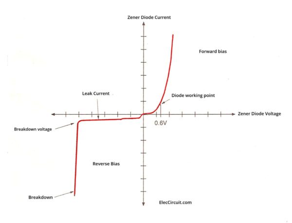
For example, a 1N4001 Diode has a breakdown voltage at 50V, etc. But the Zener diode has this low voltage level, depending on the properties of the Zener Diode.
When considering the reverse bias, in the graph. In the lower range of the breakdown voltage level. It will have a small amount of voltage and current, flows through it.
And, due to the leakage current in the Zener diode. But this current has a very small amount. So, it does not affect the work of Zener Diode.
Are you get a basic idea?
Let’s see the example circuit diagrams that we use this idea. We use it as a voltage detector it is so easy but helpful.
- Simple Voltage Level Indicator using Zener diode
- Simple 12V transistor switching power supply
- Automatic battery charger circuit
What is the Zener Diode comparable to?
For the first time, I did not understand how it works. But when I saw the image below. I clearly understand. Are you the same as me?
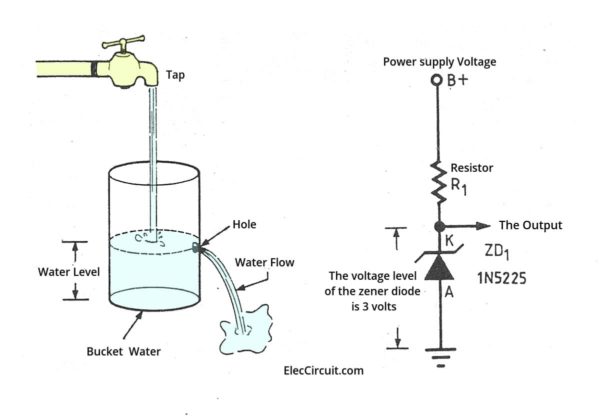
Imagine a Zener diode that looks like the can is punctured. Look at the block diagram below.
The one who knew said, the picture explaining difficult things easier to understand than text. Is it true?
Let me explain to you.
- Faucets compare with power supply.
- Water is like electricity.
- The water level in the can is comparable to Zener voltage. Which will be at the same level as the hole drilled on the side of the can
Here is a step-by-step process.
- When we open the tap. The water will flow from the tap to the can. Which has punctured the side of the can
- When the water level reaches the hole that is drilled, the water will flow out.
- The water level is constant, not likely to be higher than the hole level. So it’s the same as Zener Diode operation.
While supplying the current through R1 to the Zener diode via K, cathode, and pin A, Anode is grounded.
Zener diode part number list
Once we know the desired voltage level, we can select the Zener diode corresponding to or of similar voltage level and the appropriate wattage for our uses.
The higher-wattage Zener diode can be used instead of the lower-wattage one. But the lower one should not be used instead of the higher one. Because in a circuit with a high current, the Zener diode will generate high heat and can be damaged.
I have collected many Zener diodes over the years, but there are many more that I have heard of but never used myself. So, I am going to make a list below of the Zener diodes I have used often.
For example
3 volts ZD (Zener Diode)
If we want a 3V Zener diode, we can use 1N5225 or BZX55C3V0 with the same 3V at 0.5 watts, but if you want higher wattage use 1N4728 (3.3V at 1 watt) instead. This is the Zener diode that provides the closest voltage to 3 volts.
For other numbers:
- BZX79-C3V0 3V 0.4W
- TZX3V0B 3V 0.5W
- 1N4619 3V 0.5W
- TZX3V0C 3V 0.5W
- NZX3V0C 3V 0.5W
- ZPD3.0 3V 0.5W
- 1N4372A 3V 0.5W DO-35
- TZX3V0A 3V 0.5W DO-35
- 1N5987B 3V 0.5W DO-35
- NTE5065A 3V 1W DO-35
- BZX85B3V0 3V 1.3W
5V zener diode number
We can use 5.1V Zener Diode instead. Because we cannot buy 5.0V one. I often use BZX55C5V1, 1N5231B
See the other number below
- BZX79C5V1 5.1V 0.5W
- NZX5V1A 5.1V 0.5W
- TZX5V1B 5.1V 0.5W DO-35
- 1N751A-1 5.1V 0.5W DO-35
- BZX79-B5V1 5.1V 0.4W
- ZPD5B1 5.1V 0.5W DO-35
- 1N4733A 5.1V 1W DO-41
- BZX85C5V1 5.1V 1W
- MAZ20510AG 5.1V 1W DO-41
- BZV85-C5V1 5.1V 1W DO-41
- NTE135A 5.1V 1W
12V ZD (Zener Diode) Number
- 1N5242B 12V 0.5W
- BZX79C12 12V 0.5W
- BZX55B12 12V 0.5W DO-35
- NZX12B 12V 0.5W DO-35
- TZX12D 12V 0.5W DO-35
- NZX12X 12V 0.5W DO-35
- BZX55C12 12V 0.5W DO-35
- 1N759A 12V 0.5W DO-35
- BZX55C12 12V 0.5W DO-35
- 1N4742A 12V 1W DO-41
- BZV85-C12 12V
- 1N4744A 12V 1W 5%
Other Zener diode parts number list
- BZX55C2V0 (2V)
- BZX55C2V2 (2.2V)
- BZX55C2V4 (2.4V)
- BZX55C2V7 (2.7V)
- BZX55C3V0 (3V)
- BZX55C3V3 (3.3V)
- BZX55C3V6 (3.6V)
- BZX55C3V9 (3.9V)
- BZX55C4V3 (4.3V)
- BZX55C4V7 (4.7V)
- BZX55C5V1 (5.1V)
- BZX55C5V6 (5.6V)
- BZX55C6V2 (6.2V)
- BZX55C6V8 (6.8V)
- BZX55C7V5 (7.5V)
- BZX55C8V2 (8.2V)
- BZX55C9V1 (9.1V)
- BZX55C10 (10V)
- BZX55C11 (11V)
- BZX55C12 (12V)
- BZX55C13 (13V)
- BZX55C15 (15V)
- BZX55C16 (16V)
- BZX55C18 (18V)
- BZX55C20 (20V)
- BZX55C22 (22V)
- BZX55C24 (24V)
- BZX55C27 (27V)
- BZX55C30 (30V)
- BZX55C33 (33V)
- BZX55C36 (36V)
- BZX55C39 (39V)
- BZX55C43 (43V)
- BZX55C47 (47V)
500mW Zener Diode (Nominal Zener Voltage)
- 1N4370A (2.4V)
- 1N4371A (2.7V)
- 1N4372A (3.0V)
- 1N746A (3.3V)
- 1N747A (3.6V)
- 1N748A (3.9V)
- 1N749A (4.3V)
- 1N750A (4.7V)
- 1N751A (5.1V)
- 1N752A (5.6V)
- 1N753A (6.2V)
- 1N754A (6.8V)
- 1N755A (7.5V)
- 1N756A (8.2V)
- 1N757A (9.1V)
- 1N758A (10V)
- 1N759A (12V)
500mW Zener Diode (Nominal Zener Voltage)
- 1N957B (6.8V)
- 1N958B (7.5V)
- 1N959B (8.2V)
- 1N960B (9.1V)
- 1N961B (10V)
- 1N962B (11V)
- 1N963B (12V)
- 1N964B (13V)
- 1N965B (15V)
- 1N966B (16V)
- 1N967B (18V)
- 1N968B (20V)
- 1N969B (22V)
- 1N970B (24V)
- 1N971B (27V)
- 1N972B (30V)
- 1N973B (33V)
- 1N974B (36V)
- 1N975B (39V)
500mW Zener Diode (Nominal Zener Voltage)
- 1N5221B (2.4V)
- 1N5222B (2.5V)
- 1N5223B (2.7V)
- 1N5224B (2.8V)
- 1N5225B (3.0V)
- 1N5226B (3.3V)
- 1N5227B (3.6V)
- 1N5228B (3.9V)
- 1N5229B (4.3V)
- 1N5230B (4.7V)
- 1N5231B (5.1V)
- 1N5232B (5.6V)
- 1N5233B (6.0V)
- 1N5234B (6.2V)
- 1N5235B (6.8V)
- 1N5236B (7.5V)
- 1N5237B (8.2V)
- 1N5238B (8.7V)
- 1N5239B (9.1V)
- 1N5240B (10V)
- 1N5241B (11V)
- 1N5242B (12V)
- 1N5243B (13V)
- 1N5244B (14V)
- 1N5245B (15V)
- 1N5246B (16V)
- 1N5247B (17V)
- 1N5248B (18V)
- 1N5249B (19V)
- 1N5250B (20V)
- 1N5251B (22V)
- 1N5252B (24V)
- 1N5253B (25V)
- 1N5254B (27V)
- 1N5255B (28V)
- 1N5256B (30V)
- 1N5257B (33V)
- 1N5258B (36V)
- 1N5259B (39V)
1W Zener Diode (Nominal Zener Voltage)
- 1N4728A (3.3V)
- 1N4729A (3.6V)
- 1N4730A (3.9V)
- 1N4731A (4.3V)
- 1N4732A (4.7V)
- 1N4733A (5.1V)
- 1N4734A (5.6V)
- 1N4735A (6.2V)
- 1N4736A (6.8V)
- 1N4737A (7.5V)
- 1N4738A (8.2V)
- 1N4739A (9.1V)
- 1N4740A (10V)
- 1N4741A (11V)
- 1N4742A (12V)
- 1N4743A (13V)
- 1N4744A (15V)
- 1N4745A (16V)
- 1N4746A (18V)
- 1N4747A (20V)
- 1N4748A (22V)
- 1N4749A (24V)
- 1N4750A (27V)
- 1N4751A (30V)
- 1N4752A (33V)
- 1N4753A (36V)
- 1N4754A (39V)
- 1N4755A (43V)
- 1N4756A (47V)
- 1N4757A (51V)
- 1N4758A (56V)
- 1N4759A (62V)
- 1N4760A (68V)
- 1N4761A (75V)
- 1N4762A (82V)
- 1N4763A (91V)
- 1N4764A (100V)
3.5W Zener Diode (Nominal Zener Voltage)
- 1N1588 3.9V 10 %
- 1N1588A 3.9V 5 %
- 1N1589 4.7V 10 %
- 1N1589A 4.7V 5 %
- 1N1590 5.6V 10 %
- 1N1590A 5.6V 5 %
- 1N1591 6.8V 10 %
- 1N1591A 6.8V 5%
- 1N1592 8.2V 10 %
- 1N1592A 8.2V 5 %
- 1N1593 10V 10 %
- 1N1593A 10V 5 %
- 1N1594 12V 10 %
- 1N1594A 12V 5 %
- 1N1595 15V 10 %
- 1N1595A 15V 5%
- 1N1596 18V 10 %
- 1N1596A 18V 5 %
- 1N1597 22V 10 %
- 1N1597A 22V 5 %
- 1N1598 27V 10 %
5W Zener Diode (Nominal Zener Voltage)
- 1N5333 3.3V
- 1N5334 3.6V
- 1N5335 3.9V
- 1N5336 4.3V
- 1N5337 4.7V
- 1N5338 5.1V
- 1N5339 5.6V
- 1N5340 6.0V
- 1N5341 6.2V
- 1N5342 6.8V
- 1N5343 7.5V
- 1N5344 8.2V
- 1N5345 8.7V
- 1N5346 9.1V
- 1N5347 10V
- 1N5348 11V
- 1N5349 12V
- 1N5350 13V
- 1N5351 14V
- 1N5352 15V
- 1N5353 16V
- 1N5354 17V
- 1N5355 18V
- 1N5356 19V
- 1N5357 20V
- 1N5358 22V
- 1N5359 24V
- 1N5360 25V
- 1N5361 27V
- 1N5362 28V
- 1N5363 30V
- 1N5364 33V
- 1N5365 36V
- 1N5366 39V
- 1N5367 43V
- 1N5368 47V
- 1N5369 51V
- 1N5370 56V
Basic Zener diode forward bias and the reverse bias
The Zener diode always keeps the voltage drop across it at 3V. The remaining voltage will drop across the resistor.
Not only that, See the next circuit diagrams.
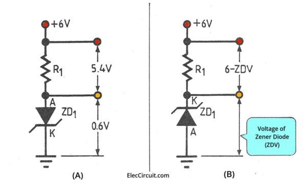
See an example of the basic Zener diode between a forward bias (A) and the reverse bias (B).
- Look at the circuit A.
When we enter a forward bias voltage. (At the anode pin has more voltage than the cathode). The positive current enters the anode of Zener Diode (ZD1) via Resistor (R1).
The operation of a Zener diode is like a general diode. It will allow the current to flow through it. And there is the voltage drop across about 0.6V. The rest of the voltage is across the resistor.
When the voltage of the Zener diode is combined with the resistor, We get the voltage equal to the power supply. - Look at the circuit B.
In contrast, when we enter a reverse bias (The cathode pin has more voltage than the anode pin) to a Zener diode.
This time, the Zener Diode will have different features than normal diodes.
The common diodes will not allow currents to flow through them.
But in this, the Zener diode will allow the current to pass through it. Only when the voltage across the bias reverse is greater than the Zener diode voltage.
In this, it works. Because the power supply is 6V. And the voltage of the Zener diode is 3V. And, the voltage across the Zener diode is constant. It is the breakdown voltage level as above.
We can change this voltage level(Vz). By changing the number of Zener diode, which the manufacturer has specified, there are many numbers and many sizes as mentioned above.
What is more? We will learn them with many example circuits below.
How to use Zener diode
Normally, Zener diode is used as the regulator circuit. There are many forms, as follows.
Simple current and constant voltage regulator
Look at the basic circuit below.
It is low current regulator circuit. Which is determined by the resistor R1. And the output voltage has a constant value equal to the zener diode voltage in any loads.
We can calculate the appropriate resistance of R1 using the formula:
R1 = (Vin – Vz)/(IL + Iz)
Most in practice. The current-Iz, while the load connected. We usually set it to 5mA. So we get a new formula.
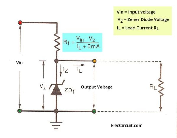
R1 = (Vin -Vz)/(IL + 5mA)
So, Choosing the resistance to depend only on the current flowing through the load. But if wanting to calculate for use in real work.
We have to offset for IZ current. While there is no load as well.
Because while there is no continue loading The current will flow through all Zener Diodes. It should allow for the wattage of Zener Diode to endure while no-load as well.
Want to see real calculate to find R1?
Read Also: 5V Zener regulator low current
Remember:
Choosing a Zener Diode. We need to look at the watts that the Zener diode can tolerate.
Which is calculated as follows:
The wattage power lost in the Zener Diode (P) is equal to the Zener diode voltage (Vz) times the current passing through the Zener diode (Iz).
P = Vz x Iz
Note: Iz is obtained from the voltage across the resistor divided by the resistance of that resistor(R).
Do you get an idea?
Basic Higher current Zener and transistor regulator
Look at the circuit below. It is similar to the previous circuit. But it can supply a higher current. Because the transistor is a helper to increase current up.
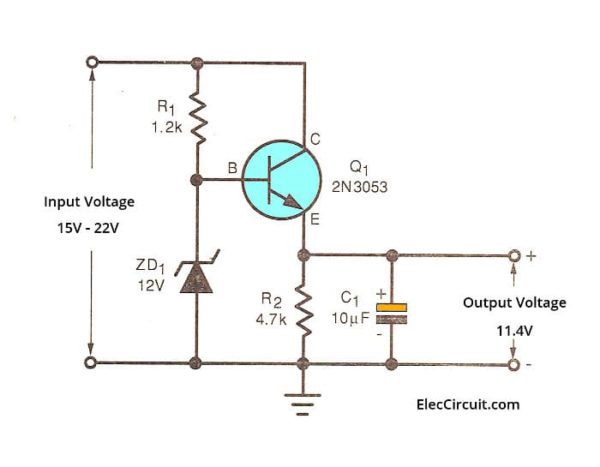
We connect it in serial before output. Then use a Zener diode voltage as a bias voltage for the Transistor. The output voltage of this circuit is less than Zener diode about 0.6V.
Because the voltage of Zener Diode will drop across between base and emitter of transistor about 0.6 volts.
The maximum current that the circuit can supply depends on the capability of the transistor.
If the transistor highly withstands to current. It can supply a lot of currents. And, on the other hand, if there is little resistance. it will supply lower current.
Parts lists
- Q1: 2N3053, 0.7A 40V NPN Transistor
- ZD1: 12V 0.5W Zener Diode
- C1: 10uF 16V Electrolytic Capacitor
- R1: 1.2K 0.25W 5% Resistor
- R2: 4.7K 0.25W 5% Resistor
Check out these related circuits, too:
- 100mA 5V converter circuit
- Small Zener diode voltage regulator circuit with PCB
- 9V regulated power supply circuit
Do you observe? The output is 11.4V only but we want 12V. How do you do?
Then, The solution to the problem is to make the output voltage equal to the Zener diode voltage.
Look at the circuit diagram. Add Diode to offset B-E transistor voltage.
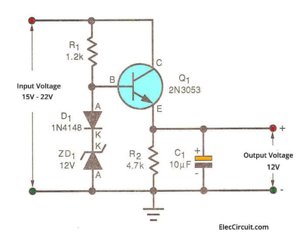
By bringing the Rectifier Diode to a series with a Zener diode. Because of the voltage across the diode, it will just offset the voltage across the pin B-E of the transistor.
The output voltage is therefore equal to the Zener Diode voltage.
Make 3V DC regulator using Zener Diode and transistor
Is it easier? If we use suitable Zener.
Look at the true circuit.
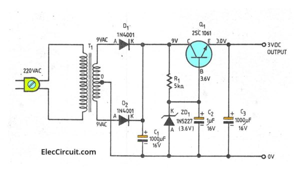
We use the Zener Diode No. 1N5227 or BZX55C3V6. It has a Zener Diode voltage equal to 3.6V.
When the current flows through the base to emitter. There will be the voltage across the base and emitter about 0.6V.
Therefore need to reserve another 0.6V. The output voltage is approximate 3V
For other devices, it has the same principle of DC power supply.
When the transformer reduces the voltage to 9V, it will pass the rectifier diodes D1 and D2 (full-wave rectifier) to be DC voltage.
Then C1 will make the DC current smoother. It passes Resistor R1 to the cathode of Zener Diode.
Next, C2 is a filter capacitor to keep stable Zener voltage. And C3 also is a filter capacitor to reduce a ripple.
This circuit can give output 3V at 800mA max.
See parts list below
- Q1: 2SC1061, 4A 40V NPN transistor
- ZD1: 3.6V 0.5W Zener diode ,1N5227 or BZX55C3V6
- D1,D2: 1N4001, 1A 50V Diode
- R1: 5K 0.25W 5% Resistor
- C1,C3: 1,000uF 16V Electrolytic Capacitors
- C2: 1uF 16V Electrolytic Capacitor
- T1: 117V/230V AC primary to 9V-0-9V,1A secondary transformer
What is more?
Voltage comparator Zener op-amp regulator
What is a better circuit?
In addition to this method, we also have a way to compare the output voltage with the Zener diode voltage. By using an op-amp as a comparator. As Figure below.
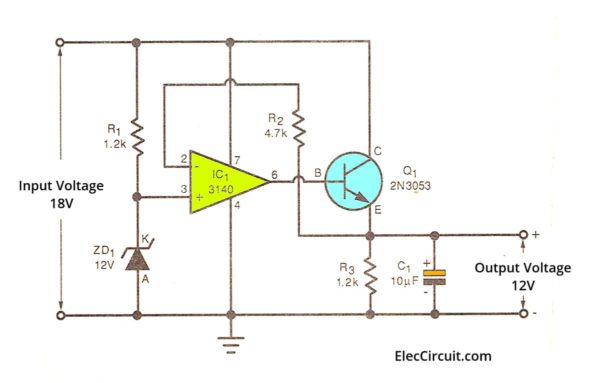
When the power goes into the input, there is a voltage across the 12V Zener diode. Therefore, pin 3 of the op-amp (CA3140) has the voltage is equal to 12V as well.
When the power goes into the input, there is a voltage across the 12V Zener diode. Therefore, pin 3 of op-amp has the voltage is equal to 12V, too.
It causes the output-pin 6 of an op-amp is a positive voltage. To bias Q1 works. So, there is the current flows through pins C-E and R3.
If pin 2 and pin 3 are higher then the voltage will come out pin 6. To bias Q1, has more current flows. Until the voltage pin 2 and 3 are equal.
We will see this circuit has high stability than only one transistor.
Parts you will need
- IC1: CA3140, 4.5MHz, Bimos Operational Amplifier With MOSFET Input/Bipolar Output
- Q1: 2N3053, 0.7A 40V NPN Transistor
- ZD1: 12V 0.5W Zener diode
- C1: 10uF 25V Electrolytic capacitor
0.25W Resistors, tolerance: 5% - R1, R3: 1.2K
- R2: 4.7K
Conclusion
We can see that the Zener Diode is used in various circuits.
Here are a few related posts you might want to read:
- Super Steady Zener diode voltage regulator circuit
- Variable zener diode circuit, adjust voltage output
- Power Supply for Audio Amplifier , multiple output 12V, 15V, 35V
GET UPDATE VIA EMAIL
I always try to make Electronics Learning Easy.
Related Posts


I love electronics. I have been learning about them through creating simple electronic circuits or small projects. And now I am also having my children do the same. Nevertheless, I hope you found the experiences we shared on this site useful and fulfilling.
I am 72 years old but I always like electronics I don’t know that much but I find it interesting.
Regards Roger.
Hi Roger,
Thanks so much for your feedback.
It makes me so happy.
Did you know that You are the same age as my father?
I promise to make electronics easy for you.
I hope my dad likes electronics like you. Because it could help reduce his memory loss. You probably have a good memory, right?
Thanks again.
Apichet
Good to be among professionals
Hi katongo,
Thanks for your feedback.
Can you explain to me why Basic Higher current Zener and transistor regulator if you should not look at resistor R1 but in transistor to give higher current. Somewhere I have read that resistor R1 is essential to give higher current to a circuit.
Hello Tomasz,
It is glad that you are interested in the power supply. I love it. Yes, In the power supply. We use a Zener diode and transistor often.
A resistor affects the current of the load as well. It passes the current to a Zener diode and most current to the load.
Then, we add a transistor. Also, a resistor is a device that passes a bias current for the transistor to operate. The more current flows through the transistor to the load.
In the past, I didn’t really understand how this works. But when trying to build these circuits, and compare them so more understandable
PS. I am not quite sure. I will clearly understand your question. My English is quite poor.
The water tank zener analogy is not really demonstrative of a zener. A better 1st order anology would be a mechanical spiral tension spring with loops at each end. Then with a bolt through it and a nut setting the max elongation of the spring(to mimic Vzener). Then some mechanism to not allow a reverse elongation as the zener will act as a regular diode if reversed.
Hi,
Thank you very much for your advice.
I’m currently studying about Zener diodes.
Your suggestions are very helpful to me.
And I will learn more.But I am a slow learner and not very good at it. 🙂
The water tank analogy as given is incorrect. The pressure (voltage) on the output is effectively zero unless the tap is so wide open that the water backs up in the can.
A can with a wide overflow at the top so that most of the water flows out will give a fixed pressure (voltage) at an outlet at the bottom of the can, but this analogy also fails because there is no excess current outlet in a Zener Diode.