You want to use a DC regulator or learn about voltage regulators using 2N3055. Why use this transistor? Normally, it can be used with loads that require a current not exceeding 2A and a voltage of not more than 30V.
This is enough for general work. It’s a transistor that people like to use for a long time. Therefore easy to find And very cheap. There is a lot of circuits using 2N3055.
Now we recommend you 2 circuit diagram. Both circuits use a Zener diode and transistor.
12V DC regulator circuit using 2N3055
Here are 12V 1A linear regulator using a transistor and Zener diode. It is a series voltage regulator because the load current passes through the series transistor.
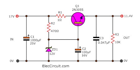
As the circuit diagram below, The input terminal wants an unregulated DC supply,15V to 20V. Then, the regulated voltage will come out to the load.
12V 1A linear voltage regulator using 2n3055 transistor and Zener diode
To begin with, An electrical current flows through the resistor-R1 to limits current to the Zener diode. So it provides the reference voltage.
In the same, the base voltage of transistor-Q1 is also a constant.
When ZD1 is 12V, the base voltage is also the 12 volts.
Recommended: What is Zener Diode and principle working
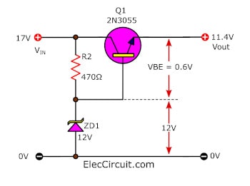
If we set the transistor in this form. The output voltage is the same as the Zener diode voltage. And we always call this that emitter follower. In practice, the voltage of output is lower than ZD1. Because when a transistor is working. It needs to has a base-emitter voltage.
- VBE = Base-Emitter voltage
- VZD = Zener diode voltage
- Vout = Output voltage
Vout = VZD – VBE
VBe = 0.6V
Vout = 12V – 0.6V = 11.4V
Look at figure you will more understand.
This voltage is still suitable for many loads using the 12V supply such as receiver radios.
Since it is a power supply that regulates a certain power output.
In the circuit, the transistor has a proper gain and changing of VBE help it.
- When a load use more current. In general, the output voltage is low down. But the base-emitter voltage rises up, transistor Q1 works more. So it keeps the output voltage to be a constant level.
- Then, if load use less current. The output voltage increase. But the output is still a fixed voltage. Because the voltage of Base-emitter less, transistor Q1 works less too.
The advantage of this circuit, we can use a tiny current to Zener diode and base of a transistor. Thus, it has a much more stabilized output.
The function of Others components
- C1 is a smoothing capacitor at an input.
- C2 keeps the reference voltage to be stable better.
- C3 is a 0.047uF decoupler capacitor to filter out the transient noise.
- R1 increases the stability of the load circuit
- Do you know what is transient noise?
The power supply has a stray magnetic field. The circuit will induct them into the transient noise. The transistor-2N3055 can power load current up to 2A. But it is so hot. It so needs a proper heatsink.
Power-loss in a series regulator circuit
Good power supply circuit design. It should reduce the loss of energy in the circuit to a minimum. Of course, energy will be expressed by heat.
In this series pass transistor regulator. The transistor-Q1 works look like a resistor. When we consider the power loss. It must dissipate or reduce it.
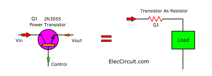
Do you see an image? It is simple. Let me explain to you.
Look at three cases below:
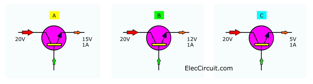
In these 3 examples, A, B, and C. The outputs are 15V, 12V and 5V. At 1A the current.
Do you know which transistor has the most heat loss? Or…
Which transistor will heat up the most?
Yes, C example. Why?
Because the reason is simple.
The transistor of C is dropping the most voltage. It is effectively a dropper resistor and must dissipate heat according to ohms law.
Here is show each case:
- In the case of A:
The voltage across the transistor (VCE) is 20V -15V = 5V.
It needs to dissipate wattage is 5V x 1A = 5W.
- In the case of B:
the voltage across the transistor (VCE)is 20V -12V = 7V.
It needs to dissipate wattage is 7V x 1A = 7W.
But…
- In the case of C:
The VEC is 20V-5V = 15V; So, the wattage is 15 watts.
Short-circuited case
If a power supply is short-circuited. The whole input voltage will be dropped across the power transistor. And it will result in enormous heating problems.
So, for this reason, we should keep it cold with an effective heat sink.
Learn: variable voltage regulator with 2N3055 transistor
38V Power Supply Using 2N3055
My friend is learning about CNC, he wants a 38V Regulated Power Supply for servo motor. We have many ways to use it, but what is best for him. This circuit is one of the right choices. Because he has all the equipment. No need to buy a new one.
How this circuit works
We use the Simple Zener diode voltage regulator as main ideas, and two transistors to increase current to the load at 1A-2A.
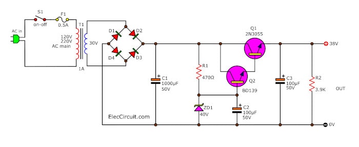
This regulated power supply included a transformer-T1, a bridge-D1…D4, and the 38V DC filtering voltage regulator circuits, which consists of C1, C2, R1, R2, R3, Q1, and Q2.
When 230VA or 120VAC (USA) is provided, step-down transformer-T1 changes the power line AC to about 30VAC. The full-wave rectifier bridge, D1 through D4 to rectifies the AC into pulsating DC, then filtered by C1.
The capacitor C1, C3 acts as the storage capacitor or filters the noise and spikes off the AC. The 40V Zener Diode-ZD1 keeps the voltage constant across the base of BD139 NPN transistor-Q1 and Q2-2N3055 as the Darlington form.
The electrolytic capacitor-C2 is used for the smoothed Zener voltage. This makes the 38V constant voltage and high power across resistor R3 and the (+) and (-) output terminals.
When the output is connected with the low resistance load, the power transistor-Q2 will get very hot, so we always use a heat sink on it.
Parts will you need
Semiconductors:
- D1-D1: 1N4002, 100V 1A Diodes
- ZD1: 40V 1w Zener Diode
- Q1: BD139, 80V 1.5A NPN Transistor
- Q2: 2N3055 or TIP3055 100V, 15A, NPN transistor
Resistors (All 0.25 watt,5% metal/carbon film, Unless stated otherwise)
- R1, R3: 3.9K
- R2: 470 ohms
Electrolytic Capacitors
- C1: 470µF 50V
- C2: 47µF 50V
- C3: 100µF 50V
T1: 230V or 120V AC primary to 30V, 1A-2A secondary transformer
SW1: Power ON-OFF Switch
F1: 0.5A Fuse
Note:
You can use the Bridge Diode 2A-4A 200V to replace D1-D4. The transformer is used 2A min for the 1-2A load.
Related Circuits:
Return to look: Transistor voltage regulator
GET UPDATE VIA EMAIL
I always try to make Electronics Learning Easy.
Related Posts

I love electronics. I have been learning about them through creating simple electronic circuits or small projects. And now I am also having my children do the same. Nevertheless, I hope you found the experiences we shared on this site useful and fulfilling.
i appreciate your helpful hints regarding understanding electronic circuits,kindly contineue mankind help.
Hello muhammad rafique ejaz,
Thanks for your feedback.
If i use 2SC5200 in this circuit instead of 3055 can i use it for input voltage of upto 60v.? I want to regulate 12v DC (10A with multiple transistors in parallel) from 48 to 60v DC. Please let me know. Thanks
Hello Xain,
Thanks for your question. Yes, if you use 2SC5200 for 60V. In here circuit: https://www.eleccircuit.com/simple-voltage-regulator-using-2n3055/#38V_Power_Supply_Using_2N3055
You need to change ZD1 30V and 33V in series. Use R2 to 1K. See more: https://www.eleccircuit.com/what-is-zener-diode/
Note: We use 2SC5200 in this circuit 0-50V 3A Variable power regulator: https://www.eleccircuit.com/0-50v-3a-variable-dc-power-supply/
Thanks a lot, too.
Apichet
nice presentation, but I don”t understand how the 2n3055 spec sheet has 7V for the veb. The circuit shows the VBE as 12volts. Is there a difference between the VBE and veb ?
Hello abdool,
I am happy to hear that my article is useful for you.
Yes, you are correct. In the datasheet VBE max is 7V.
Look at the circuit Voltage at Zener diode is 12V and V output 11.4V. So the voltage at Base and Emitter is 0.6V only.
The data sheet info is telling you the amount of voltage you can apply “without damaging the device”. Vbe = 7v, means the transistor will not be damaged if your circuit sustains a 7Volt difference between the base and emitter (but it is understood that the typical voltage drop from base to emitter is ~ 0.7v). Similar, the Vcb=100 (means you can have a voltage difference of 100 volts between the collector and base. VCE=200V, means that you can have a voltage diff of 200V across collector to emitter.
Thanks for sharing.
Hi!
In the last example there is no R3 in the schematic.
Hello John,
Yes, It is simplest circuit. It does not have 1 ohms resistor, because it makes the output lower current a little bit. However You can put it, may be 5 watts resistors. This is interested we may add overload protection. If you are interested this ideas. I and my daughter will try it. We love power supply.
How do we make variable voltage regulator with 2N3055 transistor?
Hi,
Look at: https://www.eleccircuit.com/simple-variable-dc-power-supply-0-30v-2a-for-beginners/