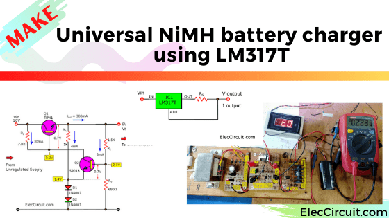
Here is a constant current and voltage AA Ni-MH battery charger circuit. I use an electric shaver almost every day. It requires an alkaline battery, but it is unrechargeable. So, I had to replace this type of battery often; it was very wasteful. You might have gone through it like me.
As time went by, the AA Ni-MH rechargeable battery’s maximum capacity increased. Thus, I switched to it instead, and it saved me some money. According to the manufacturer, we can recharge it up to 1,000 times if used properly. So, how could we do that?
Note: The content about 4+ AA Ni-MH battery charger circuits for 4 AA batteries or more, using the same principle.
I recommend it based on my experience. And it might be helpful for you. To reduce the number of mistakes and increase efficiency.
Proper Ni-Cd/Ni-MH battery charger systems
The distinguishing feature of this type of battery is that it has a constant voltage level of about 1.2V and provides a long-lasting current at this voltage level. See the graph below, comparing it to alkaline batteries.
When we fully charge, its voltage level will be as high as 1.5V and will drop quickly until reaching 1.2V.
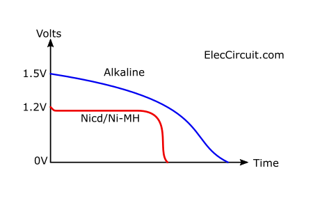
It is very suitable for circuits or loads that consume continuous current, such as motors, light bulbs, inductor coils, etc. However, it may not work well with a circuit that requires a constant voltage of 1.5V.
Recommended: Simple Li-ion Battery Charger Circuit with Automatic Cut-Off
It has a few important recommendations:
- It should be charged with a current of 10% of the capacity, or what’s called 0.1C, for about 12-16 hours.
- While this type of battery is being charged, its voltage should not exceed 1.55V.
Therefore, we should use a proper battery charger circuit according to the recommendations above.
Safer with constant current
We should charge it with a constant current. This method is easy and safe. But it takes a very long time.
For example, a 2,400mAh battery of mine has a suitable charging rate of 0.1C. Thus, we should charge it with a constant current of 240mA for 10 hours. But it actually takes 14–16 hours. Because when the battery is almost full, the charged current will be less.
If we need to charge faster, we can just increase the charging current to 720mA (0.3C). The charging time will drop to 3-5 hours.
Good sound? But…be careful!
When the battery is full, you have to disconnect the charger immediately. Otherwise, the chemicals inside the battery get too hot and may cause damage.
For me, it is better to charge at 0.1C.
Keeping the battery under voltage
While this type of battery is being charged, its voltage should not exceed 1.5V.
Imagine we are charging two 1.2V AA Ni-MH batteries. But set the input voltage to 20V. Which is too high. The charger circuit will be heavily burdened by excess voltage and sometimes the battery voltage may increase too much.
When should I charge it?
We should always use up the battery’s power completely and then charge it. Because the battery can memorize the lowest current.
I use these ways to observe when to charge by seeing if the load gets less current or by measuring the voltage of the battery. If it’s below 1.1V, then it’s time to charge the battery.
How is this useful? Read more
Related:
- Converts power supply to automatic battery charger using SCR-CA723
- Microcontroller | Digital power supply circuit, 5V 3A using LM350 or LM323
- Uses of capacitors | Capacitance | RC circuit time constant and Coupling
How to pick a charging system
Choosing components, or, as some people may call it, designing the circuit. It is a very interesting and challenging process. Sometimes it is very painful. In this case, let’s think about it in a step-by-step way.
LM317 constant current
Start by thinking about charging with constant current. We have used many ways in the past, such as
- the 7805 regulator chip,
- NPN transistor,
- PNP transistor
But this time, let’s try using LM317 chips. It is both simple and easy, just like the 7805. It is good at simple variable power supplies and some other things. If I were to explain to you all those things, this post would be very very long for sure.
So you should read this first: LM317 works pinout, and more.
Now, Let me just explain to you how to use it as a simple constant current.
See the circuit below. Yes! there only is IC and Rs. Isn’t it easy?
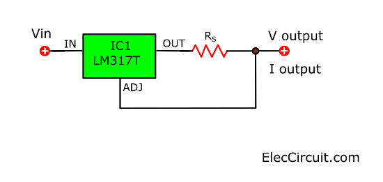
In short, we can find the output current (Iout) easily, with:
Iout = Vref ÷ Rs
Suppose we are using 10Ω as Rs.
And Vref = 1.25V
Therefore, Iout = 1.25V ÷ 10Ω = 0.125A
If we want Iout = 240mA = 0.24A
Rs = 1.25V ÷ 0.24A = 5.2Ω
You may use 5.6Ω.
Important: The input voltage should always be greater than the output voltage by 3.6V.
In this case, we are charging two AA batteries. It is 1.2Vx2 = 2.4V. Thus, the input voltage should be 6V.
With this level of voltage, the LM317 works at its full capacity. It will have less excess energy. There is almost no chance that the voltage of each battery (while charging) will exceed 1.5V at all.
Recommended: Recycle Free Li-ion battery from E-waste
Regulated voltage Power supply
The input voltage of the regulated power supply should be 6V 500mA. Both to maintain the efficiency of the circuit and reduce the chance of overvoltage for a Ni-MH battery.
In this circuit, we have many regulator ICs to choose from, such as 7806, 7805, or even LM317. They are easy to use.
But for today, let’s instead use a transistor circuit because we already have the transistors and other components. We can also learn to calculate the components. Even though this kind of circuit is old. But if we already have it, we should at least try to learn it.
Here is a step-by-step process.
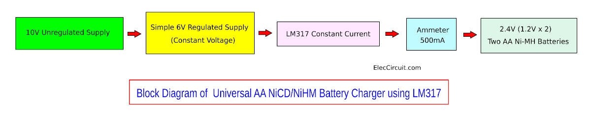
- 10V unregulated Supply
Almost all electronic projects that use the AC Main Circuit must use this part. It is a simple DC power supply circuit. That is easy to design. - Simple Voltage Regulated Supply
It is Series Regulator with adjustable output voltage to make a constant voltage. - LM317 constant current
It is an easy circuit. Why? read below. - Ammeter
Shows the amount of current flowing into the battery and knows that the connection points are normal. - 2 Batteries in series
Let’s get started.
500mA DC Unregulated supply
The above simple regulator circuit requires the input source as DC unregulated supply.
Normally, a transistor regulator circuit requires an input voltage more than the output voltage of about 3.5V. Thus if the output voltage is 6V, the input voltage should be 9.5V up.
It means that we need to build a 9.5V unregulated power supply. Look at the circuit below.
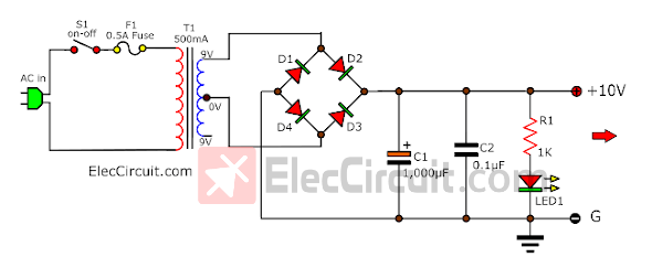
It has a 9V transformer, If no load the DC output voltage is about 12.6V
When we use a battery with a size of about 2.4V and not more than 200mA. It is advisable to use the DC power supply 12V 300mA. Set …
- The voltage of the secondary winding is 9V at 500mA.
- Capacitor-C1 is the filter to smooth voltage. We use a 1,000uF 25V electrolytic capacitor for this current.
Related circuits about battery chargers
- Constant current battery charger circuit
- Simple Ni-cad battery charger with little parts
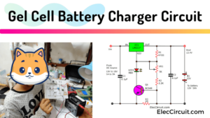
- Make Gel cell battery charger circuit
Then, we look at a simple regulated circuit. To adjust the voltage in all 3 levels above
It is a Series Feedback Voltage Regulator circuit that uses a transistor and a Zener diode.
Learn more: Series Regulator with adjustable output voltage
So what?
Here is a step by step to calculate roughly this circuit only. But it is enough for practical use.
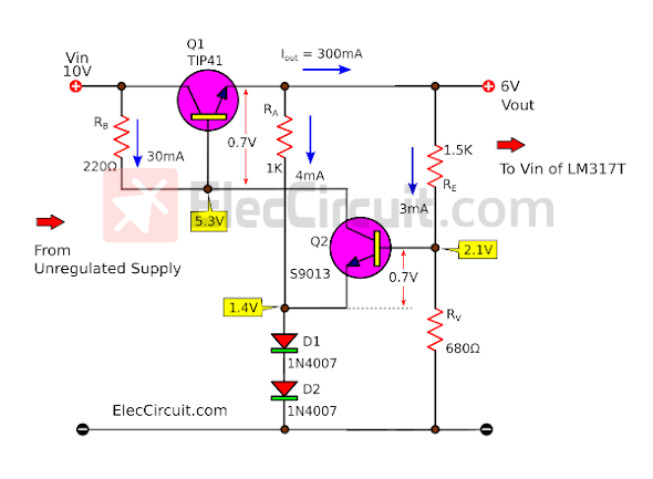
RB?
When Vin = 10V, Vout = 6V, VBE = 0.7V, IRB= 20mA (20mA to 30mA)
Get VB = Vout – VBE
VB = 6V – 0.7V
= 5.3V
Find RB = (Vin – VB)/ IRB
RB = (10V – 5.3V)/20mA
= 235Ω
Use RB = 220Ω
RA?
Some current of Vout is a bias current of Both Diodes-D1-D2 of about 4mA. So, the current flows RA (IRA) of 4mA.
VD1D2 = 1.4V
It is a way to find RA = Vout – VD1D2 ÷ IRA
RA = (6V – 1.4V) ÷ 4mA = 1.15K
But the resistor is not for sale. Therefore, we use a 1K resistor instead.
We will see that the bias current of the Diodes is still 4mA. Though Vout is lower than 10.3V.
Because… When Vout reduces. And the current of RA is lower, too. But the current of RB is more. So, the bias current Zener diode is 5mA.
Do you understand?
RE?
Then, set IRE(the current of RE) is 3mA, VBE = 0.7V, VD1D2 = 1.4V
VRE = Vout- (VD1D2+VBE)
= 6V-(1.4V+0.7V)
= 3.9V
So, we can find RE = VRE/IRE
= 3.9V/3mA
= 1.3K
Use RE is 1.5K
RV?
Vout = 6V, VD1D2 = 1.4V, IRV = 3mA, VBE = 0.7V
VRV = VD1D2 + VBE
= 1.4V + 0.7V
= 2.1V
RV = VRV/IRV
= 2.1V/3mA
= 700Ω
Use 680Ω
Then, we merge all parts together to become the complete circuits below.
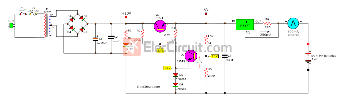
We add LED1 to show circuit power on. And R8 is limiting the current resistor of LED1.
Plus we add an ammeter to indicate current charging into the battery. At first, it read high current. But when the battery is full we read it is zero.
We can select the voltage to charge the battery by SW1.
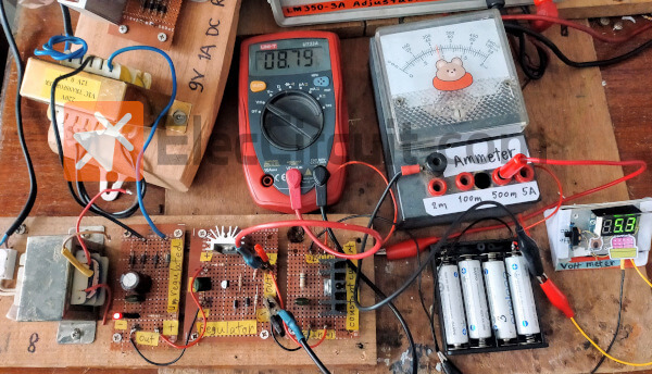
How to build
Since this project has quite a few parts. So, we may assemble them on the universal PCB or perforated board. You should check the diagram well before charging the battery.
4 AA Ni-MH battery Charger circuit
Our friend (Alessandro) asked “Very interesting. What kind of modification should be applied if one wants to charge 4 NiMH batteries in series?” It was very easy to do. I’ve tried it and it works pretty well.
Let’s look at the idea of choosing or customizing the circuit. All of these come from real circuit experience and may not be perfect but can be further developed
The batteries that are charged are 4 AA 2000mAh Ni-MH batteries while they are in series with a normal total voltage of 4.8V at 2000mAh. And they have a maximum safe (not hot) voltage of about 6V.
We use the same because it charges the same 2,000mAh battery. But we also need to find its Vin in order to properly determine the battery charging voltage level. Since the battery voltage is 4.8V. So, the Vin is 8.4V (from 4.8V+3.6) or about 9V.
We should use the 9V regulated voltage Supply circuit. We only calculate the new RE value. And change the Vout from 6V to 9V as well.
Then, set IRE(the current of RE) is 3mA, VBE = 0.7V, VD1D2 = 1.4V
VRE = {Vout- (VD1D2+VBE)}/IRE
= {9V-(1.4V+0.7V)}/0.003A
RE = 2300 ohms = 2.2K 0.25W
The original 10V voltage level is no longer enough for a regulated voltage power supply circuit, it requires 12V or more.
We need to change the voltage level of the transformer from 9V to 12V because when converting to DCV, the voltage level is about 14V to 17V.
We test charging the battery. At the beginning, the battery voltage level is about 5.2V. After almost 10 hours the voltage level rises to 6.0V. And the charging current drops to 180mA. It indicates that the battery is full.
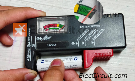
We try to take it out to check with a battery tester, it has full power.
9V 800mA Ni-MH battery charger circuit
This circuit can be easily adapted for use with a 9V 800mAh Ni-MH battery.
LM317 constant current
We should use a charging current of about 0.1C or about 80mA.
Resistor R6 = 1.25V ÷ 0.08A = 15 ohms.
For Vin = 12.6V ( from 9V + 3.6) or 13V
Regulated voltage Supply
We should use the 13V output. We only calculate the RE.
Then, set IRE(the current of RE) is 3mA, VBE = 0.7V, VD1D2 = 1.4V
VRE = {Vout- (VD1D2+VBE)}/IRE
= {13V-(1.4V+0.7V)}/0.003A
RE = 3,633 ohms = 3.9K 0.25W
500mA DC Unregulated supply
The original 10V voltage level is no longer enough for a regulated voltage power supply circuit, it requires 12V or more.
We need to change the voltage level of the transformer is 12V to 15V because when converting to DCV, the voltage level is about 17V to 21V.
Conclusion
We experimented with building this circuit. and using it works quite well. In the future, a full-voltage detection circuit and a timer circuit may be added in conjunction with the timer. for ease of use. If friends try to build it And what kind of result came out? Don’t forget to share Or any other suggestions are welcome.
Not only that you may like these projects
- How to discharge Ni-Cd battery
- Automatic NiMH battery charger circuit
- Simple NiMH NiCd Battery Charger circuit
Related Posts

I love electronics. I have been learning about them through creating simple electronic circuits or small projects. And now I am also having my children do the same. Nevertheless, I hope you found the experiences we shared on this site useful and fulfilling.
Very interesting. What kind of modification should be applied if one wants to charge 4 nimh batteries in series?
Hi,
Yes, you can do it.
But you should recalculate the entire component because it uses a higher voltage of 4.8V batteries. But it’s not too difficult. It’s fun. Unfortunately, we don’t have any 1.2V x 4 batteries available. Hope you enjoy it. If it has any effect, feel free to share it with us.
Thanks
Hi, thank you for this clear instruction!
In your calculation for Rb you put “Get VB = 6V + 0.7V = 10.9V”, I don’t see where you got that 10.9V from.
Could you clear that up for me?
Hello, dear friend!
Thanks for the correction.
We have already rewritten this calculation.
God bless you.
Apichet&Kids
I would like to charge 9Volts 800mAH Ni-NH battery will the same circuit work and what should be the charging voltage
Hi,
Please look at: https://www.eleccircuit.com/nicad-battery-charger-by-ic-lm317t/#9V_800mA_Ni-MH_battery_charger_circuit
We hope it can help you.
Thanks