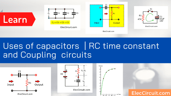
I am going to explain to you learn basic uses of capacitors, Capacitance. We can use RC time constant and coupling circuits.
This is an ongoing content from Capacitor Principle working. I believe that you already understand it.
Of course, it is a small device. But it is very important in various electronic circuits. Some principles are something that should not be overlooked.
Connection of series and parallel capacitors
Sometimes we need to use capacitors that have different capacitance from the standard values. We are not able to use adjustable capacitors. Because it is too small.
A good solution is to connect in parallel or in series until you get the capacity you want.
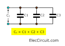
Parallel Circuit
Often we will connect them in parallel like this. For example, in the power supplies, filter circuits, etc.
The total capacitance is the sum of all capacitances.
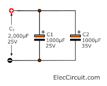
We should not use a lower voltage than actual use. Otherwise, it will get damaged. It gives the total capacitance of 2000uF to 25V. It will withstand high voltage levels. Just the lowest level is 25V.
For example, you build a DC power supply circuit but it has a high ripple. Because of low capacitances filter.
We should add more capacitance. Previously, I only have 1000uF 25V and 1,000uF 35V electrolytic capacitors.
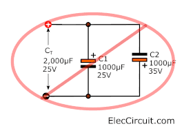
Caution: Should not connect the wrong polarity. It will damage the electrolytic capacitor, the wrong electrical connection.
Recommended: Learning electronics for beginners
Series Circuit
Sometimes we may need to connect the capacitor in series. We can calculate the total capacitance in 3 cases as follows.
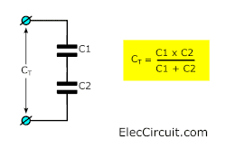
Two Capacitors
The total capacitance is the produce of the two capacitances divided by their sum. See formula!
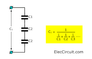
Three or more capacitors
In the series circuit, we can find CT with this formula. Look:
if each capacitor has the same value. The total capacitance is the one capacitance divided by N. The N is the number of capacitors that are connected in series.
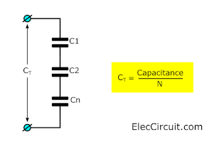
For example, 3 capacitors, 0.1 μF 100V.
CT = 0.1 μF ÷ 3 = 0.33 μF 300V.
Notice We can see that the rated voltage of total capacitances increases according to the capacitors. Likes, 300V capacitors from 3x100V.
Read next: Surge protection circuit for power supplies
Charge and energy stored
I quite don’t like math. Because many times the calculations are difficult to confuse. But of course, the electronics we love, are part of science in physics. Always use mathematical principles. I believe that difficult things consist of simple things together. So we gradually learn together.
Total charge (symbol Q) stored on capacitors can be found from:
Charge, Q = C × V
Since:
Q = charge in coulomb (C)
C = capacitance in farads (F)
V = Voltage in volts (V)
When it charges, capacitors store energy by:
Energy E = ½QV = ½CV² where E = energy in Joules (J)
Please be noted that Energy in the capacitor to be returned to the circuit.
It does not convert electrical energy into heat like a resistor. The energy stored by the capacitor Much less energy stored with batteries. Therefore, it cannot be used as an energy source.
Understand capacitive reactance Xc
The capacitive reactance (symbol Xc) is the resistance value of the capacitor via AC (Alternating Current) is measured in ohm.
But reactance is more complicated than resistance. Because its value depends on the frequency (f) of electrical signals passing through the capacitor (C)
Capacitive Reactance, Xc = 1 / 2πfC
Since:
Xc = reactance in ohms
f = frequency in hertz (Hz)
C = capacitance in Farads (F)
Xc reactance is high at low frequencies and low at high frequencies. For constant DC current which has zero frequency. Xc reactance value is infinite (maximum resistance).
Therefore, as a rule, capacitors allow AC to pass, but it will block DC.
For example
A capacitor of 1µF has a reactance of 3.2kΩ at a frequency of 50Hz. But at higher frequencies. For example, at 10kHz, there is a reactance of only 16Ω.
Note: The Xc symbol is used to represent the reactance of a capacitor. The XL represents the reactance of the inductor.
The most important difference is that XL increases with frequency. (In contrast to Xc). And if both XL and Xc are connected in the circuit. The sum of reactance (X) is the difference between the pair.
Learning RC time constant
Charging of a capacitor
The capacitor (C) in the circuit diagram is charged from the voltage source (Vs), with the current flowing through the resistor (R).
The voltage across the capacitor (Vc) at the beginning is zero. But will increase as the capacitor starts to charge.
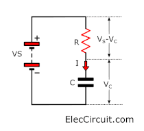
The charge will be full when Vc = Vs. The charge current (I) is determined by the voltage across the resistor (Vs – Vc):
- Charge current I = (Vs – Vc) / R (if Vc voltage increases)
- But at first, Vc = 0V. So, the beginning current Io = Vs / R
- Vc increases instantly when the charge (Q) begins to occur (Vc = Q / C). It causes the voltage drop across the resistor to decrease. and the charge current will also decrease.
- That means the charge rate will continually decrease.
Meet the time constant
What is the time constant for an RC circuit? It is measuring the time that the capacitor charges the current through the resistor. Yes, it need work with both capacitor and resistor or RC network.
We can easily calculate the time constant with the formula:
Time constant = R x C
Note:
- Time constant has units of seconds (s)
- R is the resistance, has units of ohms (Ω)
- C is the capacitance, has units of Farad (F)
Time constant experiment
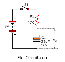
Let’s look at an example circuit.
When we press S1. The current will flows to C1 through R1 slowly. Then, we use the voltmeter to measure the VC. It will be VS or about 9V when time is the time constant.
Or we use the formula to find the time.
We will find the time constant from R1 x C1.
= 47K x 22 μF
= 1,034mS = 1.034S
Learn Charging of capacitors
If the high time constant means the capacitor will slowly charge. We will notice that the time constant comes from the properties of capacitance and resistance in the circuit. Not just the properties of capacitors.
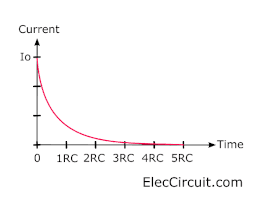
Looking charging current
The time constant (RC) is the time taken for the charging (or discharging) current (I) to fall to 1/e of its initial value (Io). ‘e’ is an important number in mathematics (such as pi). so we can roughly say that the time constant is the time taken for the current to fall to 1/3 of its initial value.
After each time constant. The current will drop by 1 / e (about 1/3)
Do you understand? I will explain to you the illustration. Look:
After 5RC, The current falls to less than 1% of the initial value. And we can say that the current is fully charged. But in reality, the capacitor will be fully charged forever.
Look at VC voltage
We try to observe the voltage in the capacitor in the table.
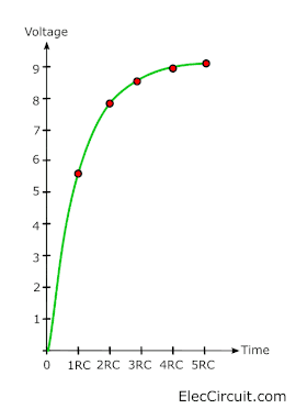
Increase in voltage (V) when charging occurs In the beginning, the voltage will increase quickly. Because the current has a high charge. But when the current starts to decrease the charge will start to slow And the increase in voltage is also slow.
| Time | Voltage | Charge |
| 0RC | 0.0V | 0% |
| 1RC | 5.7V | 63% |
| 2RC | 7.8V | 86% |
| 3RC | 8.6V | 95% |
| 4RC | 8.8V | 98% |
| 5RC | 8.9V | 99% |
The graph shows the voltage that is charged in a capacitor during a time constant.
Discharging of capacitors
When the capacitor discharged. The Initial current (Io) is determined by the initial voltage across the capacitor (Vo) and resistor (R) as follows:

Initial Current Io = Vo/R
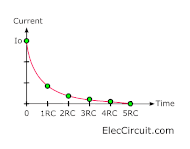
Meet the current
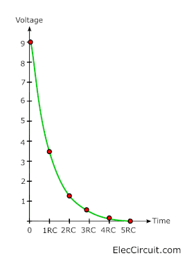
We notice that the charge and discharge current of the capacitor graph is the same. This graph is an example of exponential decay.
See the voltage
When we measure the voltage It will keep decreasing at a time constant rate. See in the table.
Looking at the graph will make it easier to understand.
Initially, the current will be very high because of the high voltage.
So, the charge will run out quickly and the voltage will decrease rapidly too.
| Time | Voltage | Charge |
| 0RC | 9.0V | 100% |
| 1RC | 3.3V | 37% |
| 2RC | 1.2V | 14% |
| 3RC | 0.4V | 5% |
| 4RC | 0.2V | 2% |
| 5RC | 0.1V | 1% |
When the charge is depleted the voltage will reduce. It causes a low current. So, the rate of discharging becomes slower and longer.
After the 5 time constant (5RC). The voltage across the capacitor is zero and we can say that the capacitor is discharged completely.
Even if actually the release will continue forever (Or until the circuit changes)
Using capacitors
We can use capacitors for many purposes:
- Control timing —for example, used with IC timer 555 to control charging and discharging
- Smoothing —for example, in the power supply
- Coupling —-for example, connecting the audio system and speakers
- Filtering — for example, in the bass-treble tuning circuit of the audio system
- Tuning — for example, in a radio system
- Store energy —for example, in circuits, flashes, cameras
Read others: I learn uses of capacitors from Capacitance @ https://electronicsclub.info/ This website is so good teacher for me, and you.
Capacitor coupling (CR-coupling)
In general large electronic circuits. It usually consists of many sections together. Each section is connected by the capacitor.
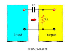
Because the capacitor allows an AC signal (change) to pass. But blocks the DC signal (stable). This connection is called a coupling capacitor or CR-coupling.
We often use to connect between sectors of the audio system. To pass through the audio signal (AC) without the voltage (DC) passed. For example, connecting speakers in an OTL amplifier or Preamplifier circuits, and more.
The precise characteristics of the coupling capacitors are determined by the time constant (RC).
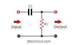
Note: The resistance (R) may be Within the part of the next circuit(the output) instead of the resistor.
The success of using coupling capacitors in audio systems.
Meaning that the signal must not be distorted or very distorted.
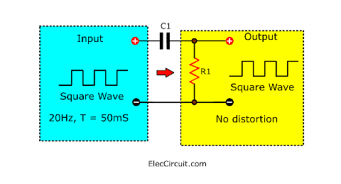
By using the time constant (RC) greater than the time period (T) of the minimum frequency of the sound signal required (usually 20Hz, T = 50ms).
Output in 3 cases of the time constant.
RC > T
When the time constant is much greater than the time period of the input signal.
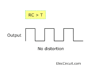
The capacitor doesn’t have enough time or is unable to charge and discharge. The signal passes without any distortion.
RC = T
When the time constant is equal to the time period of the input signal.
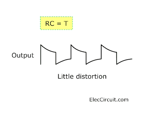
The capacitor will have time to charge and discharge before the signal changes. For this reason, the signal passing through the CR-coupling is distorted.
Please notice! Changing suddenly of the input signal that passes the capacitor to the output.
RC < T
When time constant is much smaller than the time period of signal input. The capacitor has full time to charge and discharge after each sudden change of the input signal.
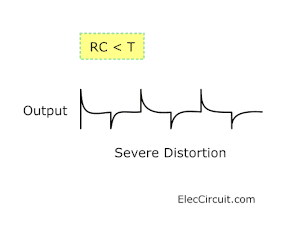
It only affects the sudden change through to the output and appears as spikes alternately with positive and negative.
This can be useful in systems that need to detect sudden changes in signals.
…
Download This
All full-size images of this post as PDF are in Ebook. Thanks, support. 🙂
GET UPDATE VIA EMAIL
I always try to make Electronics Learning Easy.
Related Posts

I love electronics. I have been learning about them through creating simple electronic circuits or small projects. And now I am also having my children do the same. Nevertheless, I hope you found the experiences we shared on this site useful and fulfilling.
Adorei e gostei muito, mas muito mesmo,sobre este Tutorial ( Usos de Capacitores) Grato.
Hi Antonio Rodrigues Brandão
Thanks for your feedback.