This is how to modify an old Lead-acid battery charger or convert the power supply to an automatic battery charger form. To protect battery overcharging.
We use a simple circuit with a comparator circuit.
It uses CA723 regulator and power SCR cut off the current controller.
The working principle
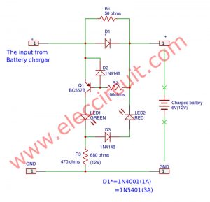
In the circuit diagram of this project. The output current will start or stop charging the battery. Because it checks voltage drop across the battery.
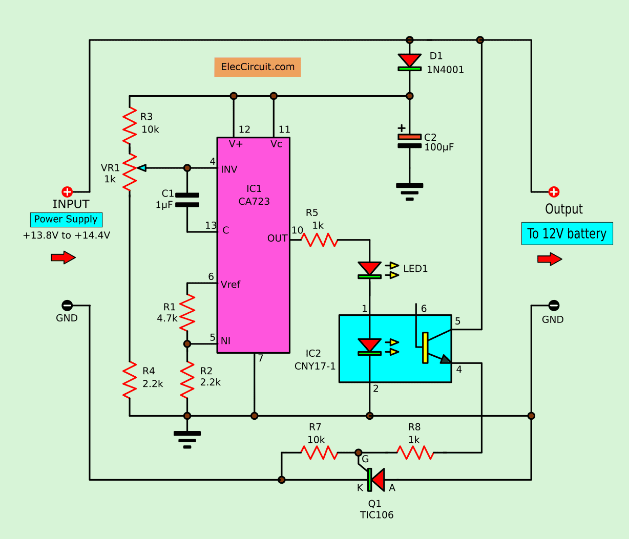
Circuit diagram of the automatic battery charger
If the voltage across is less than 13.8 volts. The circuit will begin charging. But the voltage rises to 14.4 volts. The circuit will stop automatically.
When the battery is fully charged. The circuit will stop. Because the voltage across the battery is too high.
That is the voltage across the battery Are equal to the input voltage. The voltage comparator circuit internal IC1 will acts to stop the Q1.
The adjustment voltage regular of IC1 will get voltage through the diode-D1 which is applied current about 10 mA.
Then the reference voltage divider circuit inside IC1 will get to dividing the voltage down to 2.2 volts. by R1 and R2.
Which this reference voltage will be compared with the battery voltage that is adjusted from VR1.
Using 723-IC and SCR
If the voltage of the battery is low, output pin 10 of IC1 is a logic level is “1”. Make LED1 light ready the working of optocoupler of IC2.
To connect the power motivate SCR, to work as the operation of optocoupler-IC2. It would have current to recharging the battery.
Learn: How SCR circuit works
Which this Q1 also acts as control Amount of charging current. When voltage at the battery higher up will cause voltage across the SCR (Q1) between cathode and anode lead no different.
That meant have voltage is zero volts. Making Q1 stop conducting current is stop charging and will start recharging, when Q1 conduct current again because the battery voltage lower than 13.8 volts.
The voltage detection of battery and the recharging will detected voltage across Q1 or the differences of voltage at cathode and anode lead and adjusted charging level at 14.4 volts to offset be lose inside Q1 about 1 volts
How to builds
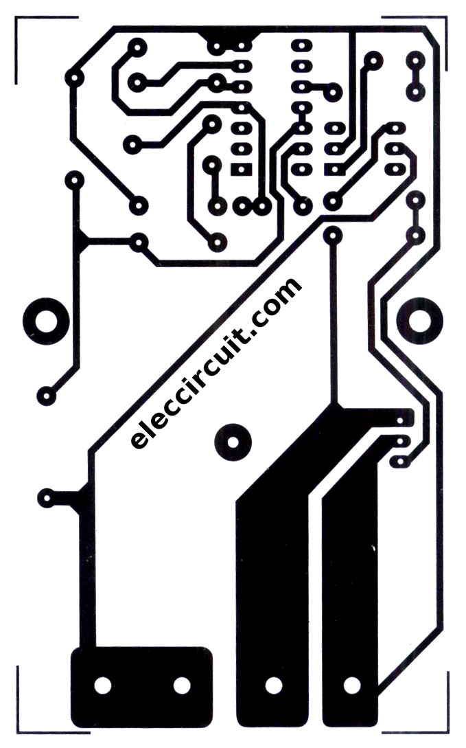
This project does not difficult over your try. You can assemble them on universal board. However, you can view the PCB layout.
The PCB layout
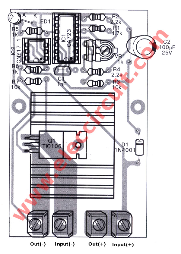
And the components layout of this project.
Recommended: Recycle Free Li-ion battery from E-waste
Customization and deployment
To begin with apply the battery you need charging in circuit, secondly, apply voltage of 13.8-14.4 volts to input of this circuit. Then use voltmeter to measure voltage across battery. To check voltage if it is lower than 13.8 volts we will don’t see LED1 glow.
Next, rotate VR1 in left slowly until see LED1 glow. It is shown that ready the circuit start charging to the battery. The voltage across battery have voltage rise up to 13.8V.
Then rotate slowly VR1 to right until LED1 go out. That is stop charging and automatically working between charging and discharging, now ready to using.
This circuit can apply charging current to 1 A and maximum 5 A.
Recommended: Simple Li-ion Battery Charger Circuit with Automatic Cut-Off
The parts you need
Resistors size ¼W +-5%
R1: 4.7K
R2, R4: 2.2K
R3, R7: 10K
R5, R6: 1K
potentiometer
VR1: 1K
Capacitors
C1: 1nF polyester
C2: 100uF/25V Electrolytic.
Semiconductors
LED1: LED as you want 3 mm.
D1: 1N4001 – 1A 50V Didoe
IC1: CA723 DC regulator IC
IC2: CNY171-1
SCR1: TIC106 power SCR 5A 400V
Others Heatsink, Socket, PCB, etc.
GET UPDATE VIA EMAIL
I always try to make Electronics Learning Easy.
Related Posts

I love electronics. I have been learning about them through creating simple electronic circuits or small projects. And now I am also having my children do the same. Nevertheless, I hope you found the experiences we shared on this site useful and fulfilling.
Thank you for sharing such a good post, hope to see more post weiahflrygds.
Hi Battery,
Thanks your feedback.
Pls. Help me sir..Can i connect output in input battery? So that my input battery never lowbatt
hi,
may i ask what is the voltage in the input?
DC or AC. or a power supply of what rating is connected.
what is the input ?? like i m giving 15 V …. what output i will get..plz help me…this is my project in college…thanks in advance 🙂
If I use a 15 Vdc, 30A power supply and a 40A SCR, can I charge one 100A , 12V battery?
Thanks for reply!
Hi I need 723ic scr battery charger circuit
Pcb sampal 1
Thanks jayantha
Dear Sir:
I would like you to send me the PCB of this Lead Acid Battery charger because I find it difficult to use the PCB programs. I would pay the cost of the same and the shipment via mail. The payment would do so through payment at destination. Thank you.
Why are two leds shown in the circuit diagram but only one on the pcb layout?.
Hi,
The LED other one is in IC2.