Do you have ever seen the xenon flash? It looks remarkable, stimulates the interest very well. Understand these to improve your skills. I trust you can do it.
There are 3 xenon flash circuits. Although, these are easy and not more. But you may like it as a good basic teacher.
First, let’s look at the Xenon Flash Tube in the common store. There are 2 forms, U-shape and I-shape. Both have the same working principle.
Meet Two Xenon Flash Tube Shape
Look at the basic structure of the Xenon Flash tube below.
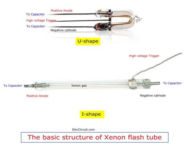
Let me explain to you how it works in a simple way.
Inside the glass tube containing xenon gas. When there is a high DC voltage across both lamp terminals. (Positive Anode and Negative cathode) Then, It ionizes the gas into light energy.
But we need the light energy to come out quickly as needed. Therefore having to feed thousands of volts pulse signal to a high voltage trigger terminals too.
Since we want It emits maximum light only for a short time. Therefore have to store energy first And then released at once.
After that, the circuit will gradually keep electricity before releasing it to it again.
So what? Do you want to see more circuits? to understand how it works.
Simple Xenon Flash circuit
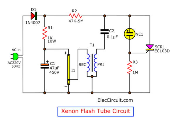
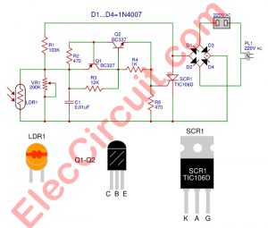
Look at the circuit below. This is the first circuit. Do not worry about it. Although use AC main and SCR.
How it works
We will learn them in a step-by-step process:
First of all, AC main comes to D1 to rectify AC to DC.
Related: Learn how AC to DC rectifier works
Then, R1 reduces a current down to charge in C1.
At the same, some current flows to R2 to charge C2. And, it will flow through the Pri coil of T1. This is a pulse transformer.
While C2 is charging. Its voltage will rise up continuously. Until the voltage rises up to one level. Makes Neon lamp(NE1) conducts a current. This voltage is about 90V.
So, it has the current to the gate of SCR1. Makes SCR runs too.
Then, the electric charges in C2 discharge through SCR1 and primary coil of T1.
Trigger coil transformer
Look at image T1. Some called the trigger coil. Though small but it can increase the high voltage at primary winding. It is a type of step-up voltage transformers
It causes electromagnetic field induction to Secondary winding of T1. This produces a high voltage pulses is thousands of volts in a short time.
These pulses activate the Xenon Flash Tube. It ionizes Internal gas to conduct electricity. So the whole energy of the C1 is emitted to L1 with all.
We will see the most light in one time and then stop.
Then, C1 start to charge new again and C2 too. And when the voltage of C2 rise up until NE1 can conduct current. The SCR1 also runs. So, I1 lights up again.
Recommended: Read more how SCR works
It works repeatedly like this, so we can see the I1 blinking in a continuous rhythm.
The time of each blink depends on R2. If low R2 time to charge C2 full or to be 90V is faster. And fast blinking too. In contrast, if a high R2, it will blinking slow down.
Parts you will need
- SCR1: EC103D, 0.8A 400V SCR
- D1: 1N4007,1A 1000V Diode
- I1: Xenon Flash Tube
- NE1: Neon lamp
- R1: 1K 10W Resistor
- R2: 47K to 5 M Resistor (See text)
- T1: Pulse transformer
- C1: 33uF or 47uF 450V Electrolytic capacitor
- C2: 0.1uF 630V Mylar capacitor
- Others: PCB, wires, AC and more.
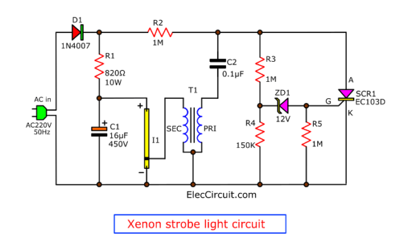
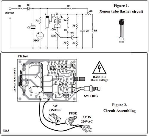
Xenon Strobe Light Circuit
Here is the second, 220V xenon strobe light circuit. It looks similar to before circuit. I do not want to waste time. You too, right?
Do you notice the difference?
Let’s learn how it works
We use ZD1(Zener diode) instead of a Neon lamp. Here is a basic process.
When the voltage of C2 is about 90V. It causes a voltage of the cathode of ZD1 is more than 12V. So, it has the current into the gate of SCR1. Makes SCR1 runs. And T1, C1, and I1 emit the highest light. Same as the first circuit.
Why we use ZD1?
According to the characteristics of Zener diodes, used as a device to check the voltage precisely. And longer using life.
Read next: example use Zerner diode to check voltage
Also, change R2 to control the speed of flashing.
Parts you will need
0.5W Resistors, tolerance: 5%
- R4: 150K
- R2, R3, R5: 1M
- 820 ohms 10W Resistor
- C2: 0.1uF 100V Mylar Capacitor
- C1: 16uF 450V Electrolytic Capacitor
- SCR1: EC103D, 0.8A 400V SCR
- ZD1: 12V 0.5W Zener Diode
- D1: 1N4004 Diode
- I1: Xenon Flash Tube
- T1: Pulse transformer
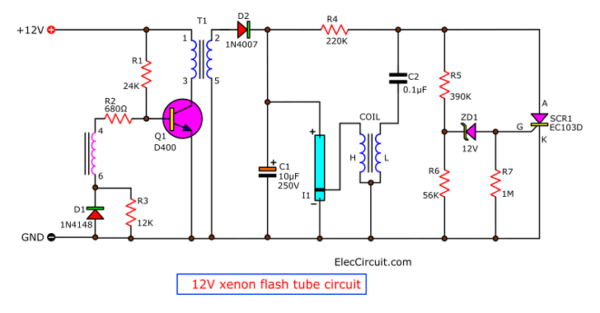
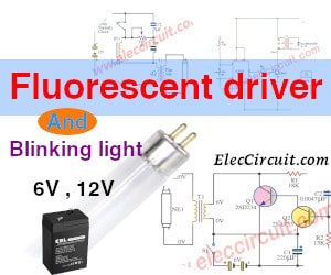
12V Xenon flash tube circuit
Imagine you have a car. You want to impress your friends with decorative lights that are not boring. Sure, Xenon flash tube is a good choice.
But before the circuit, we use it with AC main. Can you use it with DC 12V?
Yes, you can.
Look at the circuit below. I believe that you are observant.
How it works
We add the boost up voltage converter circuit. Or a tiny inverter circuit. It turns 12VDC(input) to 200VAC(approximately). They consist of 6 components, Q1, T1, R1, D1, R1, and R3.
They are a simple oscillator. To produce frequencies to drive small transformers, T1.
You will see that a high voltage, but so low current. Sure, it is enough for our xenon tube.
Learning a tiny inverter is so interesting. But it has details that may be difficult to understand. I promise to make it easy for you. Please follow me.
If you see it in another way. This circuit looks like a switching power supply circuit.
Read Also: Example Buck/boost converter circuit
What is more?
Then, more other components they look like both circuit before. Please back to read again. It will be a lower value. Because they use a lower voltage. However, another principle is the same.
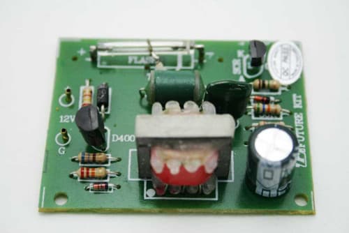
How to build
These circuits are easy and quite small. So you can build it on universal PCB. Or you can buy it at store near your house.
But…Be careful some point use AC main and high voltage. Thank you for your safety. I care about you.
I want to see your life easier
You may buy KIT on amazon.com. It’s more convenient for you.
Car xenon flash tube circuitCR: Image Radio Shack Xenon Strobe Tube Lamp, By AFCN
Here are a few relevant posts you may want to read, too:
- Quick Learn Basic Electronic Components
- 20 LED Rear Bike Light Flasher circuit using 555
- Music dancing light circuit,4500 watt using opto isolator
GET UPDATE VIA EMAIL
I always try to make Electronics Learning Easy.

I love electronics. I have been learning about them through creating simple electronic circuits or small projects. And now I am also having my children do the same. Nevertheless, I hope you found the experiences we shared on this site useful and fulfilling.
Hi Prajit, I really like your project pages (like this one – xenon tube). Your style is very direct and concise. It doesn’t matter that your English is not quite perfect, it is easy to understand. Well done, and please keep up the good work. I will follow your advice on how to support you, buying from links etc. Good Luck.
Hello, Michael Avison
Thanks for your feedback. Is it really? My English easy to understand. I will keep it up.
Thanks again
Apichet and Prajit (My mom)
question with a xenon 500 v. 2000 j lamp what size capacitor would you suggest for max. discharge I used your strobe light schematic but went with a step down transformer 110 v to 12 v with a bridge rectifier can you help thanks ..WAYNE
Hello WAYNE MITCHELL,
Thanks for your question. It’s very disappointing. If I understand your question is not clear. My English is poor.
You try AC main voltage from 110V to 12V with DC unregulated power supply. Then you use this circuit. https://www.eleccircuit.com/wp-content/uploads/2019/11/12V-xenon-flash-tube-circuit-1.png
You can use this circuit. Yes, may try it.
But I not sure when you use 110V input. In my country use 220V AC main.
However, I want to see you finish this circuit.
Thanks again.
Apichet.
How can I calculate the value of R2 to have a 10Hz output?
Hello Andrew,
Thanks for your visit. I am happy, you feel interested in this circuit.
But I am sorry. To be honest, at the moment, I don’t know the formula for calculating the R2 value to determine the flashing speed you want. So I used to change R2 to a potentiometer. Or Try changing the resistor value.
However, I believe in the future. We’ll figure out how to find the value of R2.
Thanks
hi dear;
everything is ok and informative.
thanks a lot.
amir kurdistani
Hello Kurdistani,
Thanks for your feedback.
Thanks for your sharing. Great job!!
Here I have a question:
I want to add a series inductor to the xenon lamp as a damping. The peak current is about 150A and average current 0.2A. the inductor value is in the range of 90n. Could you suggest what inductor I should use for the purpose? For you info, the lamp I am using is BHN2647, the discharge capacitor is 100uH and supply is 240Vac after a bridge rectifier.
Thank you very much!!