This is car dc to dc converter project for converts from 12V car battery to dual voltage of +40V Ground and -40V (Available of +/-27V ; +/-30V ; +/-30V; +/-50V as setting parts) are used as power supply of 50W-100W amplifiers.
When you want to increase your car amplifier. Essentially, there are 3 ways in the design of power amplifiers that operate with a 12V car battery.
Firstly, The easiest way. It is by working directly from 12V. This ways maximum output power was limited to swing voltage at output. If it is assumed that the voltage drop across output transistors of 2V. and maximum power are available when load 4 ohms is 3.2 W RMS only. If want higher power to must reduce impedance speaker lower such as 2 ohms will have a higher RMS 6W.
Secondly, this way is called that “Bridge amplifiers” By useuse the amplifiers of 2 sets, the signal phase difference is 180 degrees, There are speaker connects at between the output. The voltage swing across speaker will rise to 2 times the output power is four times higher, the maximum output power 12.5W at Load 4 ohms. Or 25W at load 2 ohms.
Disadvantages is must use 2 amplifier section per channel and power driver output is limited.
Thirdly, If want Power at higher than that The best way is to use the circuit Increase a higher voltage or a DC to DC converter. Generally used to increase the voltage of 12V into dual voltage supply in dozens of volts as the requirements of the amplifiers that can use with the direct coupling amplifiers.
The DC to DC converter to the output voltage to 40V from 12V car battery, to provided enough power for 50-100 watts RMS stereo amplifier.
DC to DC converters circuit diagram
This DC to DC converter works in switching mode. Which is higher than other methods. But in this type of design. There are several considerations.
Noise signal: Since frequency switching of circuit Therefore, necessary switching higher than the audio frequency range.In this place using frequency 50Khz, in addition to good effect in the process of high-frequency noise. Also makes Use a smaller transformer.
The device acts in switching. Select a POWER MOSFET. The first reason mosfet has a positive temperature coefficient. Therefore can be connected in parallel directly. So that there are higher power rise. Without the resistor divided current. Which resulted in loss of resistance of these wasteful.
Why the power mosfet to run faster.Therefore is low loss and high efficiency. And better reliability. And the last reason is power mosfet easy to use. Because mosfet devices species trans-conductance is controlling drain current by control voltage at gate can connect gate directly with low power circuit. Different from the Bipolar transistor., Which must control with current at base necessary must to use the preamp transistor before.
The issue of stability in the CAR battery provide voltage changes. Quite wide are May be lower than 11V until 15V. In some cases it is possible to change the voltage + – 15% of the average. The change this should not affect the output voltage of circuit.
The circuit feature.
This switch-mode power supply or DC to DC converter provide enough output power. For power amplifiers 50W 2 pcs. The maximum current 15A (typically at 1-2A). There are the cut off working when low battery voltage. For protect battery power failure can not start the car.
It also has over heat protection circuit. Since inside CAR temperature was already high. Especially when it is sunny and not cold air. If the volume is too loud. May be the case until the temperature the circuit damage.
To protect. semiconductor device. thus requires a higher temperature circuit is working on it. When temperatures drop, so continue to work normally.
This working principle
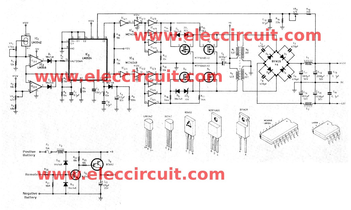
The importance parts of this circuit is a pulse width modulator IC – LM3524. The complete DC to DC converter circuit as Figure 1
This IC3-LM3524 act a switching frequencies generator to power MOSFET Q1-Q4. By have IC4 and IC5 are a buffer circuit. The oscillated frequency is set by R7 and C2 that high as double times of the switching frequency.
Figure 1 The circuit of DC to DC converter 12V to +/-40V using LM3524
The output from IC3 have 2 phase opposite. to output works as push-pull form.
In the buffer circuit include IC4 and IC5 by 4 gate digital are parallel together, to enough to driver mosfet. Which the power mosfet is each paralleled side of 2 pcs. to the high current rise. there are resistors of 56 ohms separate from each gate to equally switch, separated gate but work simultaneously. The diode and zener diode is connected between pin gate and drain protect over voltage to pin D-G of MOSFET.
See: 36 Hobby Electronic Projects
The power mosfet Q1,Q2 and Q3,Q4 will switch working to provides the current to a N1 and N2 coil in sequence. Which is primary coil of transformer T1.
The coil of N3,N4 is the secondary. Which has amount of turn than the primary coil to step up voltage rise. Then through to the bridge full wave rectifier circuit D6,D8 and filter to smooth by the output capacitors to get the DC voltage +/- 40V.
The DCV from output is feed back to R19,VR3 come to IC3 to controlled the width of pulse to control the switching,is making the A steady (DC) voltage.
The IC1-LM334Z acts to check temperature work together with IC2/1 to cut the operation of IC3 ,when the temperature higher than presetting. which has VR1 is determined. And IC2/2 acts the operation when voltage battery lower than presetting which is determined by VR2.
The capacitor C4 and Diode D3 act as a soft start system to partially started operation of the circuit.
Next, we see the transistor Q5 and Q6 are circuit to controlled the working more,and act on-off working of circuit that high current.
The coil L1,L2 and L3 use to protect high frequencies from circuit to other parts.
How to build this project
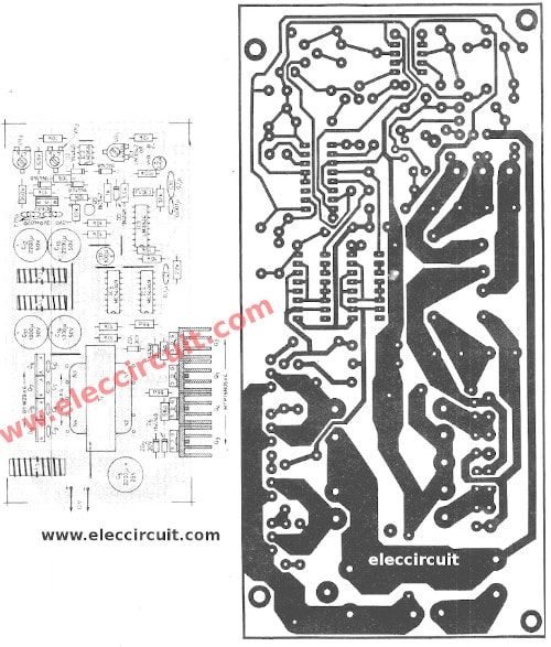
Figure 2 The PCB and components layout which have to use very much the circumspection.
T1 and L1,L2,L3 are main parts that must use great attention.
The L3 coil: Winding wire diameter 1.25 mm. Length of 1.5 m. on toroidal core size 24mm X 15mm. X 10mm. at 27 turns.
The L1 and L2 : use winding diameter 1mm. Length of 2 m. toroidal core size 22mm. x14 mm. x8 mm. at 37 turns The transformer-T1 use EI ferrite core size 50mm x 42mm x 15 mm. (EI 50) with EI plastic transformer bobbin as shown Figure 3 The S stands for “start” and F of the “finish” means the end. Hgaitgai numbers refers to a set of coils.
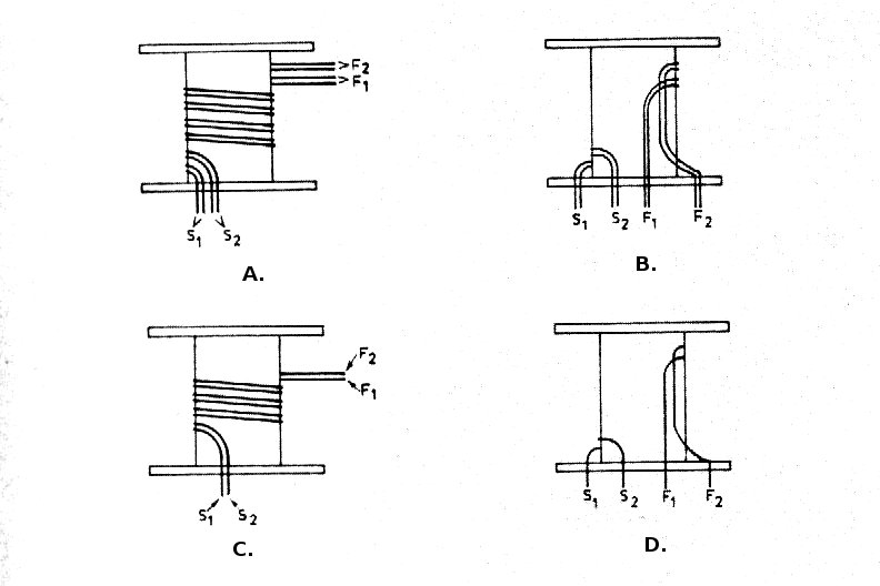
Figure 3 show how to bind T1-transformer and L1,L2,L3 coil
Start at the primary coil use the winding wire diameter 1.25 mm. Each coil wire two lines. and, bing together with the second coil, and then bind and 4 lines, 5 around half. Then bind with mylar insulation to thousands of secondary next coil.
The secondary coil use winding wire same size. (1.25 mm.) This side use single wire But bind together the two coils, that bind together two lines as Figure 20 rounds, then pull down the end of point as Figure 4, then wrapped insulation over again.
Next Rub end of entire wire, easy to solder. And check by ohm meter to certainty. Then Soldering the connector all. Next, glued heat resistant well.
Figure 2 PCB layout and components layout.
Figure 2 shown PCB layout and placing all transistor Q1 to Q4 and diode D6 to D8 should install the proper heatsink and has Insulation as short circuit protection.
The IC1 is temperature sensor should install at Power MOSFET.
Recommended:
- 0-50V 3A Variable Power supply Project
- 300W – 1200W MOSFET Amplifier for professionals only
- DC Voltage Doubler and Voltage Multiplier Circuits working
How to set the circuit
The main point to be adjusted with the 3 points are The first point VR3 adjusts the output voltage to + / – 40V. In which first adjustment to adjust VR1 clockwise until it stops. and VR2 clockwise rotation with first.
VR2 Use to adjust the lower battery voltage. Should be set to 11.5V with the use of the adjustable voltage power supply instead of the battery 11.5V. Supplied to the converter then use voltmeter measure output. Adjust VR2 clockwise until the output voltage is approximately 0V.
VR1 adjusts the temperature exceeds the cut. Defined as the temperature at 95 degrees Celsius. By examination of voltage across R1.How to calculate the the ambient temperature at that time 273 (Absolute temperature.) then Multiplied by the Reference voltage from IC3 at pin 16, then be divided by 368 to be divided voltage is in the range 4-5 volts. To adjust VR1 until voltage across R1 equals the calculated voltage.
For the remote point you probably well known. At this point in the on – off power supply or turn off the amp itself. To Use this method. Because consumers circuit currents up to 15A (max if the job is on average 2-3A). Which requires a very large switch, wiring and large, which remote when connected to a positive power ON the projects.
How to use many voltage amplifiers
If bring the DC to DC converter to use other amplifier series when same voltage supply. But if different voltage supply change number of cycles of secondary. coil For example If voltage supply +/-27V = 15.5 turns ; +/-50V = 21.5 turns.
And Increase the rate of withstand voltage of capacitor that filter current output.
And modify R19 by calculate voltage across R18 = 2V
The components List
Resistors 0.25W 5%
R1,R7: 12K
R2, R6, R10, R11, R12, R13, R20, R22, R23: 10K
R3: 6.8K
R4: 1K
R5: 15K
R8: 1.5K
R9, R21: 100K
R14, R15, R16, R17: 56 ohms
R18______22K_____1 pcs.
R19______360K____1 pcs.
Capacitors
C1,C3,C10,C13,C16__0.1uF 50V__Ceramic___= 5 pcs.
C2___0.001uF 100V polyester ___1 pcs.
C4___2.2uF 16V_____1 pcs.
C5___2200uF 25V electrolyte___1 pcs.
C6-C9___470pF 100V ceramic___4 pcs.
C11,C14__1,000 uF 50V electrolyte___2 pcs.
C12,C15___2,200uF 50V______2 pcs.
C17___100uF 25V___electrolyte__1 pcs.
Semiconductor
D1-D5,D10,D11___1N4148______7 pcs.
D6-D9____BYW29__________4 pcs.
ZD1,ZD2___Zener 30V 0.5W___2 pcs.
Q1-Q4_____MTP16N05_______4 pcs.
Q5__BC547___ 45V 100mA NPN Transistor___1 pcs.
Q6____BD682____PNP Power Transistor____1 pcs.
IC1____LM334Z__3-Terminal Adjustable Current Sources___1pcs
IC2____LM358___Dual Operational Amplifiers ___1 pcs.
IC3____LM3524__Regulating Pulse Width Modulator___1pcs.
IC4,IC5____MC14049____Hex Buffer CMOS____1pcs.
Others
T1 see text
L1,L2,L3 see text.
VR1___470 ohms___potentiometer
VR2,VR3___4.7K______Potentiometer
F1-Fuse 15A,
Socket 8,16 pin
etc….
Related Posts

I love electronics. I have been learning about them through creating simple electronic circuits or small projects. And now I am also having my children do the same. Nevertheless, I hope you found the experiences we shared on this site useful and fulfilling.
Hi I would like to get 30v dc 50ma from 6volt dc input.
Like the one mentioned in
https://www.eleccircuit.com/tag/6v-dc-to-12v-dc-converter/
https://www.eleccircuit.com/the-many-dc-to-dc-converters-using-ic-555/
So if any one who can help me plz email me on [email protected]
I don’t able to find mtp16n05 in market, please suggest me some substitutes of MOSFET.
Please
U can use p80n55 mosfet
i want to design a circuit with following specifications:
o/p voltage: 40v DC
o/p current: 60-80Amp
please suggest me the circuit for this design.
Hi, rohit
Thanks for your feedback.
Now I not have the circuits as you need.
It is too many current output.
Hey Nice job :D.
What would be most convinient if i need several output choises ? one output and select by feedback or one feed back and several output posibilities ?
Sincerely
Klavs.
Thing ypu very much
It was good
He,
For my amplifier I need +40v and -40V. But the already done product from amazon are only supplying +40v. How can I solve this?
I want to make a simple dc-dc converter of following specifications.
Input: 12 VDC from a battery.
Output: 5 VDC +/- 5 %
Output Power: 5 Watt
Service: 24X7 Continuous Duty.
Please advise me a proven circuit.
Thanks.
you can use 7805 for this plane
Hi reza es,
No, In circuit diagram does not have 7805 IC.
I want dc to dc converter schematic
Voltage selector switch
30v to 40v
3 ways or 4ways
I need above things urgently
Appreciated if you can help to find
I want a full working of this circuit..for project presentation purpose..can anyone help me with that asap..
Thanku
I want complete unit of this. 12 v to 50 v. Working machine. Can anyone help me??
Thank you so much for this important circuit
please I want to make this circuit to set up in my car, I want the PCB and schematic pictures in clear photos.
Oh hij heeft ook muziek op.
Point at ‘roadbreak’ AND CYCLE/ROUTE. You can do a shorter ROUTE>CYCLE and use triangle/square/sine.