These are 555 DC boost converter circuits. Why use them? Suppose you get these problems. Low voltage! Too high! or need to turn polarity and more. There may be many ways to solve these problems.
But today let me recommend these DC to DC converter circuits.
This is an isolated DC to DC Converter circuit in digital. In using a digital measurement circuit to connect with other circuits.
If the primary voltage is 5 V, but you want a higher voltage between 9V to 12V.
This circuit may solve your problem!
It can converter a DC 5V input into DC 7.5V to 12V output at 50mA current.
Important! it is an isolated style makes a good performance.
They include a few parts, a 555 timer, small transformer, Zener Diode, and more in a simple circuit.
It may help you.
How it works
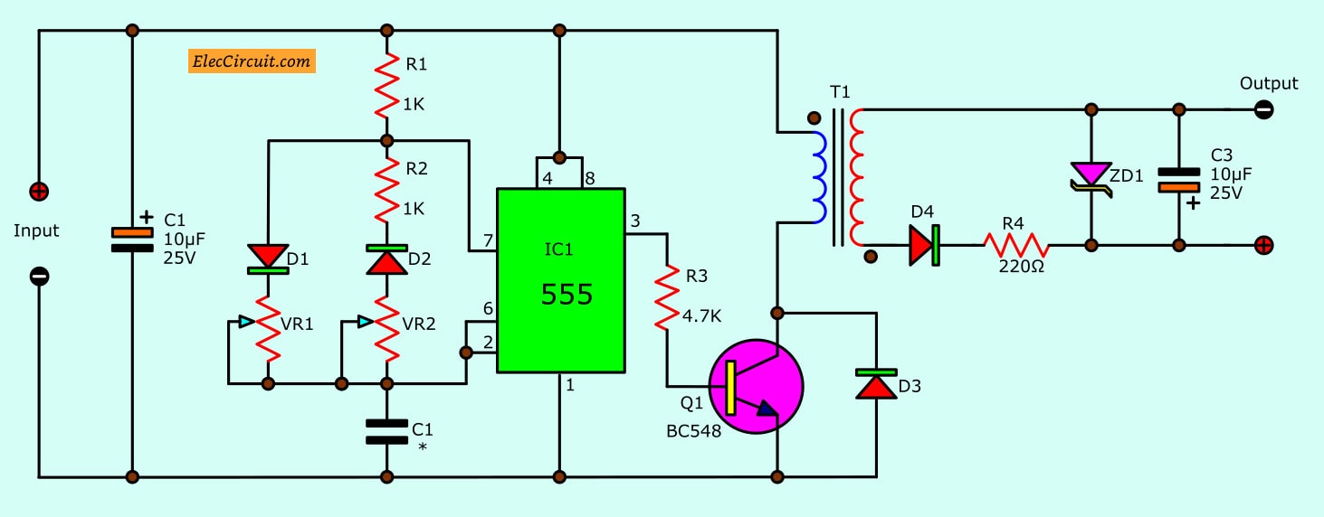
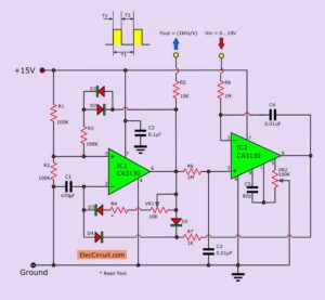
Circuit diagram of 555 DC converter for digital
On circuit consist of an astable Multivibrators using a 555 timer. They will control the power supply is on and off. To drives a transformer-T1 through the transistor Q1-BC547.
The output voltage of the secondary coil is rectified by D4 (in half-wave). And filtered with the capacitor C3. Then there is the Zener diode-ZD1 as act regulated voltage.
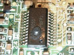
Warning: Do not use power supply over 15V because of IC1 get damaged.
Transformer-T1 It is a 1:1 ratio pattern. You can look at these transformers in many using. For example, To control an SCR and a small radio transformer, etc.
Each type of transformer is suitable for different frequencies and pulse width.
SCR transformer is suitable for a frequency of 100 kHz.
Audio frequency transformers, as well as approximately 0.5 to 40 Hz.
VR1 and VR2 To adjust the frequency and pulse width of the output oscillator.
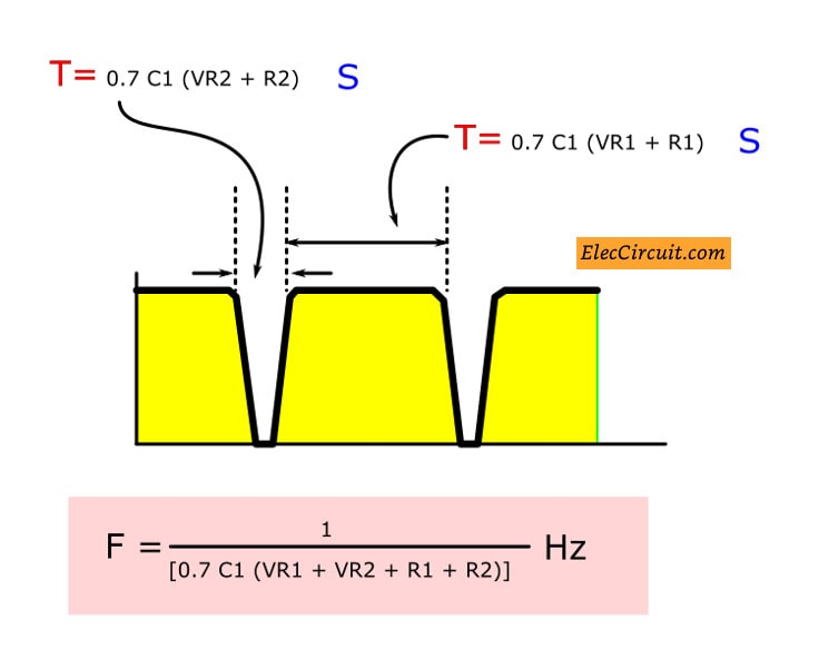
Then, look at the Figure below. The frequency waveform includes two-time width.
Charging Time is controlled by VR1, R1, and C1.
DisCharged Time is controlled by VR2, R2, and C1.
While Diodes D1, D2 set a direction of the current each time.
The frequency of the circuit can get by:
F = 1/[0.7C1(VR1+VR2+R1+R2)] = Hz
How to find a frequency of Output DC pulse of 555 oscillator
Zener diode ZD1 To set the output voltage. For example, 7.5V, 9V, 12V max.
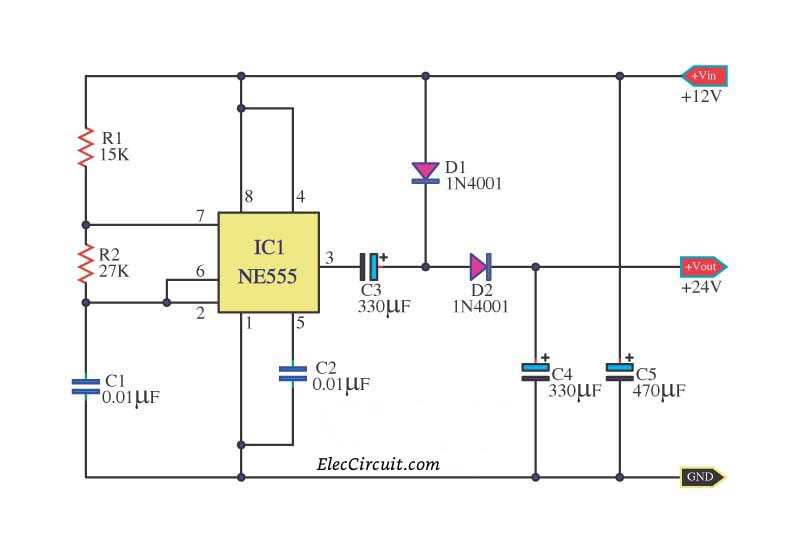
This is Simple Doubler Voltage circuit, from voltage 12VDC to be 24VDC. Use the IC highly popular number, a NE555 timer. And other a few pieces of devices too.
DC doubler voltage 12V to 24V using NE555
It can give current get about 10mA-20mA. The circuit requires a low current and unstable.
The Circuit Principle works
When using Volt input 12VDC give with the circuit will touch filter current smoothly with increasingly.
The capacitors C5 give with IC1. The resistor R1, R2, and capacitors C1.
Which builds the circuit model astable multi-vibrator Square wave generator. At the frequency of about 2KHz comes out the way pin 3 of IC1.
By having capacitors C3, C4 diode D1, and D2. Which build be boost up voltage x 2.
Which will increase the voltage level at the output in the direct current about 24VDC. Or 2 times of the level Voltage input.
Imagine we have an AC adapter for various electronic circuit experiments. But it is a single power supply with only positive voltage.
Perhaps some circuits may require a negative voltage supply, too.
What can we do? This circuit may be our good choice.
How does it works
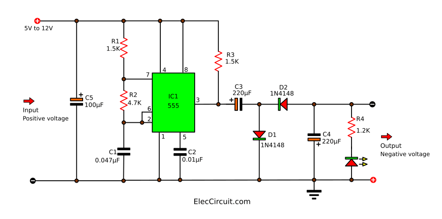
It can convert the positive voltage from the AC adapter to the negative output.
Look: in the circuit.
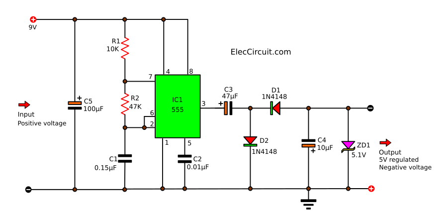
Of course, we use IC1-555 like the above circuits with R1, R2, and C1. They are A stable Multi Vibrator form, and its output is a square wave. It is a positive signal pulse frequency of 2.3 kHz at output pin 3 of IC1.
And C3 and D1 connected to the CLAMP circuit. They serve from a positive pulse to a negative pulse signal.
Then, the D2 and C3 act negative pulse signals are converted direct current (DCV) electrical signals in negative. So, the output voltage a negative DC electrical.
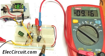
Then, assemble this circuit on a breadboard, measure the output voltage, and compare the results when you include LED or remove it. See in photo below.
We will see that with LED, the output voltage is about -9V, but no LED is -11.3V. It worked for me.
-5V Negative voltage regulator for 9V battery
Sometimes, we want to test the circuits that require a -5V negative power supply. But we have only the 9V battery.
How to change 9V battery to -5V. Sound good?
Let me explain why this circuit can do?
Look in the circuit
Like the above circuits, NE555 runs a square wave at an output of about 6V.
When the output is a positive pulse. Then, C2 charges the voltage through D1 to the ground.
And if the pulse is negative. The capacitor C2 will discharge through diode D1 and capacitor C3.
This we get negative voltage is about-6V. And there is Zener diose to keep a stable voltage, -5V. With output current approximately 5mA max.
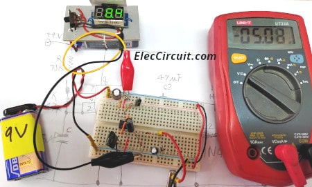
Then, assemble this circuit on a breadboard, measure the output voltage. See the photo below.
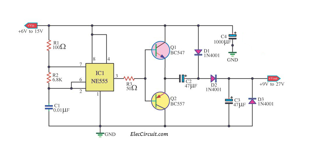
Simple Dual Power supply from single supply
I like to try different circuits by using an adapter as a power source.
But it has some disadvantages. Imagine we learn about 741 op-amp works.
We cannot use that adapter. Because the op-amps require a three-terminal power supply, positive and negative and ground.
I want you to try this circuit below.
Although, It gives a low current of power, lower than 10mA.
Let me explain you.
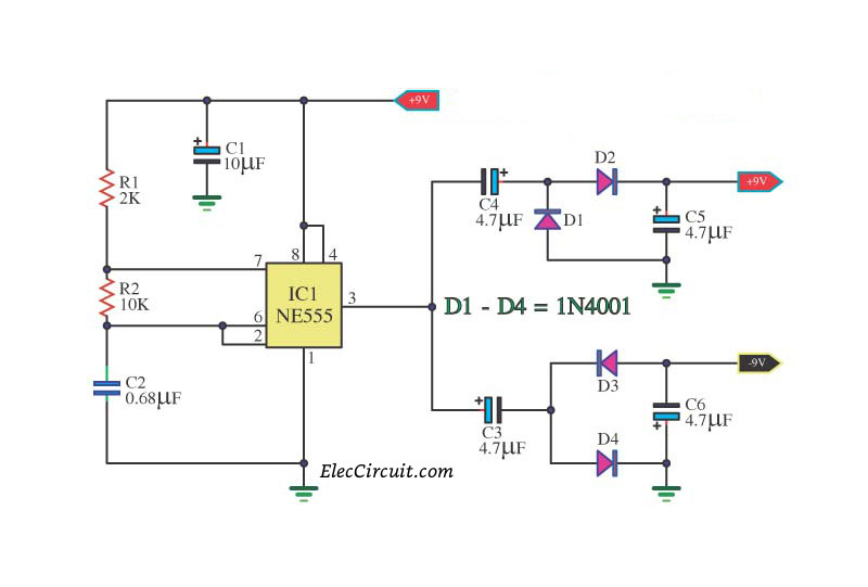
The NE555 in a stable multivibrator circuit produces a frequency rectangular wave about 100 Hz out of pin 3.
This Pulse signal passes C3 and C4 before to rectifies to DC voltage. They have both positive and negative, +9V and -9V.
Positive power supply will work with the rectifier D1 and D2. When a positive signal to be via D2 to the output.
And filtered by C5 to filter the voltage to smooth again. If there is a negative signal, D1 will pass it to the ground.
In contrast, the negative part, Both D3 and D4 are the rectifier. When a negative signal to the output signal to be via D3. And will be filtered from C6 to smooth again. And D4 will a positive signal to the ground.
I love electronics. I have been learning about them through creating simple electronic circuits or small projects. And now I am also having my children do the same. Nevertheless, I hope you found the experiences we shared on this site useful and fulfilling.
I am looking for a schematics for some extremely low power (just a few µA) 3.3 V to +/- 15 V step up NE555 circuit and would appreciate any link/tip/hint.
Do you have any schematic diagram of a circuit that produces only either 4mA,8mA,12mA,16mA,or 20mA with a constant 24vdc supply?badly needed. .:-( thank u so much f u have one.
Hi
My small project consist of building a circuit that supply a 48 volts lamp controlled by an astable NE555..the use : Blinking lamp on top of telecom tower.
Thank you
hi sir, for the Power supply of positive-negative-ground from a single power supply, can I use the input supply of 5v and generating +/-5v on the output side??
Thanks
In the second circuit i am not able to get the actual output… Input is 12V n it is not stepping up the input.. what should i do? Plzz help me its very much urgent!
Hi: Do you sell the tv/radio jammer that can go through a wall (20-30) total distance? It is cable tv. My neighbour turns on his radio/tv at 0500 am every morning. It is away to loud as I do not even have my hearing aids in. How much?
Tx
Hello Sir. I just want to ask how should I do with the Ground when I solder the circuit on a circuit board? Can I just simply leave it empty? Thank you.
all circuits are principal . . . they don’t with count nor apply to all input power range
— the bad point here is that the oscillator may not successfully function at
!! also nothing regulates the output
. . . otherwise they’re correct
► the order to proceed here is ::
• confirm your oscillator works near even duty
• confirm the output cascade saturates
• confirm the complement switch (transistor) closes (preferredly) just before the opposite starts conducting signifficantly !!!!!!!!!!!!!!!!!!!!!!!!!!!!!!!!!!!!
( • make sure the capacitor used for switching can handle twice the input voltage and is a low ESR one )
Hi sir
I need a DC relay with auxiliary contacts of different levels of voltage that act to open another circuit but the input voltage must be between 150 to 250 v
Gracias por la información tan completa. Quiero preguntar como puedo obtener 1.5 vcc sacándolo de un cargador de 5vcc porque quiero alimentar una recorta vellos de nariz y orejas que trabaja con 1.5VCC para no usar pilas. Agradezco mucho la información que puedan proporcionarmen. Un saludo.
Hi, can this Simple Dual Power supply from single supply able to supply voltage of 36v DC and 10 Amp provide I use DC power supply of 36v and 10 AMP?
The two red + voltage are they same for source and out put and can be connected together?
Since my English is quite poor. So I may be able to misunderstand your content.
It might be difficult to get high currents up to 10A at 36V. I have never tried to design a circuit at that level.
But I believe You are capable enough. Try modifying T1 and transistor power.
I feel very greatfull and helpfull from this 555 projects you have shared. Am just a beginner in electronics and it has helped me a lot to understand even at my level. Thanks again
Also can you sure some projects if any on tl494 and sg3525 pwm circuits.

nice circuit…. working fine on multisim
Respected sir,
i have 24 vdc how can i change in to +24vdc and -24vdc pls give me a circuit idea
Thank you
I am looking for a schematics for some extremely low power (just a few µA) 3.3 V to +/- 15 V step up NE555 circuit and would appreciate any link/tip/hint.
Do you have any schematic diagram of a circuit that produces only either 4mA,8mA,12mA,16mA,or 20mA with a constant 24vdc supply?badly needed. .:-( thank u so much f u have one.
sir give me ckt idea of 5vdc to 24vdc how can i got
give me ckt diagram for 5vdc to 24vdc to obtain
push on push off
Hi
Please send me a diagram for 48vdc to 9vdc – max 500 ma
Thank YOU
The positive voltage from
“Power supply positive-negative-ground from a single power supply” will be 15v not 9v
I NEED A SCHEMATIC TO CONVERT -5V DC TO 24V DC
Can give the secound circuit current about 250mA?
hello,
my requiredment are input supply 0to24v dc & output 24v dc constant to oprete the 24vdc relay so, kindly provide the ckt diagram.
Thanks
Hi
My small project consist of building a circuit that supply a 48 volts lamp controlled by an astable NE555..the use : Blinking lamp on top of telecom tower.
Thank you
thanks for this schema,
Dear sir,
i need to design the power supply from input 24Vdc to +&- 15Vdc output.please send me circuit diagram if u have any or guide me.
i need 5v to 24v dc converter circuit .help me
sir,how to convert 5v dc to 24v dc using 555timer send me the circuit help me by sending the circuit diagram
volts looks good but i need to see the amps looking for a 20amp unit???
i think the second circuit has a mistake , the pnp-npn pair will make a short circuit path through
(pnp emitter – pnp base – npn base – npn emitter)
this can be avoided by placing a resistor at each of the two transistor bases instead of shorting them together.
Can someone please send me a simple circuit for DC TO DC 12VOLTS STEP DOWN TO 3.7 VOLTS THX
hi sir, for the Power supply of positive-negative-ground from a single power supply, can I use the input supply of 5v and generating +/-5v on the output side??
Thanks
hi in the voltage doubler circuit if i give 6v does it give out 12v
Hi, vasudev
Yes you can use but this low current about under 50mA.
hello i need a circuit from 9v to 24v. 24v impulse only for one second is enough.
thx
I ask you that “when you want 24Vdc and you have 12Vdc as input you can use over current 50ma”?
Hi,
Thanks for your feedback.
Yes, You can use it.
But the current may lower than 50mA.
Please look others circuit : https://www.eleccircuit.com/simple-dc-to-dc-step-up-converter-using-tda2822/
In the second circuit i am not able to get the actual output… Input is 12V n it is not stepping up the input.. what should i do? Plzz help me its very much urgent!
What’s advantage by using 555 over using simpal two diode doubler circuit…?
will it works on a current of 6 or 7 amp.
I am looking for help to create simple circuyit to generate 24 vdc 24 w or less using 3 9vdc battery. Any suggestion
I want build 24 vdc power output using three 9 vdc battery.
use a 24v regulator (such as 7824 on heatsink ) need to be rechargable batteries at 1A load
hello sir
i in need of on solution of my project.
please give me diagram of 12 v 1amp dc power supply in which converts 3 way of 12 v 1amp power supply each.
thanks
hello
im looking for a schematic for a 20V dc to a 5V dc 1A converter switch mode power supply please.
thank you
Dear sir/medam
we need a circuit for dc dc convertor
in put volt 20 to 120 out put 18 volt 5 Amps
12 volt dc to convert 36 volt dc, but why did ?
Hi: Do you sell the tv/radio jammer that can go through a wall (20-30) total distance? It is cable tv. My neighbour turns on his radio/tv at 0500 am every morning. It is away to loud as I do not even have my hearing aids in. How much?
Tx
Hello Sir. I just want to ask how should I do with the Ground when I solder the circuit on a circuit board? Can I just simply leave it empty? Thank you.
U haven’t tell how a high voltage voltage can be reduced to low like 50v to 12v etc
all circuits are wrong i tried practically
all circuits are principal . . . they don’t with count nor apply to all input power range
— the bad point here is that the oscillator may not successfully function at
!! also nothing regulates the output
. . . otherwise they’re correct
► the order to proceed here is ::
• confirm your oscillator works near even duty
• confirm the output cascade saturates
• confirm the complement switch (transistor) closes (preferredly) just before the opposite starts conducting signifficantly !!!!!!!!!!!!!!!!!!!!!!!!!!!!!!!!!!!!
( • make sure the capacitor used for switching can handle twice the input voltage and is a low ESR one )
hallo sir or madam can you help me how dc dc doubler astable multivibrator work using timer
Hi sir
I need a DC relay with auxiliary contacts of different levels of voltage that act to open another circuit but the input voltage must be between 150 to 250 v
Gracias por la información tan completa. Quiero preguntar como puedo obtener 1.5 vcc sacándolo de un cargador de 5vcc porque quiero alimentar una recorta vellos de nariz y orejas que trabaja con 1.5VCC para no usar pilas. Agradezco mucho la información que puedan proporcionarmen. Un saludo.
Hello, Jairo Vargas
Thanks for visiting.
Is your language Spanish? I use google translate.
I’m not quite sure what you told me.
You may want DC to DC converter circuit. From 5V to 1.5V. Or you may use LM317 is a 1.5V power supply it is good because it is easy and cheap. https://www.eleccircuit.com/usb-battery-replacement-by-lm317/
Thanks
Hi, can this Simple Dual Power supply from single supply able to supply voltage of 36v DC and 10 Amp provide I use DC power supply of 36v and 10 AMP?
The two red + voltage are they same for source and out put and can be connected together?
Hi, my good friend,
Since my English is quite poor. So I may be able to misunderstand your content.
It might be difficult to get high currents up to 10A at 36V. I have never tried to design a circuit at that level.
But I believe You are capable enough. Try modifying T1 and transistor power.
Sorry for being unable to provide more clarity.
Thanks again
Apichet
I feel very greatfull and helpfull from this 555 projects you have shared. Am just a beginner in electronics and it has helped me a lot to understand even at my level. Thanks again
Also can you sure some projects if any on tl494 and sg3525 pwm circuits.
Why the capacitor voltage is not shown?