This is a Simple IF AM signal generator circuit with, 455kHz output frequency. We use simple components, CMOS IC: CD4011, CD4040. And control fixed frequency using the crystal-3.579 MHz.
In the event of AM radio repairs. The basic tools that are usually found the IF signal frequency generator.
We will use it to determine the function of various sectors.

Which these circuits are often used transistors to build the frequency. But, now we will try to use an innovative circuit that used IC and crystal as the circuit below.
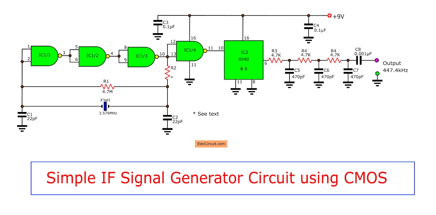
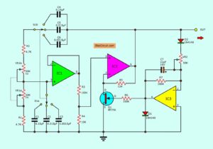
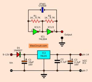
The circuit diagram of Simple IF signal frequency generator using CMOS
How it works
The working starting at IC1/1-IC1/3, R1-R2, C1-C2 and crystal are connected as the square wave frequency generators circuit. Which has a frequency of 3.579 MHz.
Then, this frequency will out to pin 10 of IC1/3, before in to pin 12 and pin 13, then out to pin 11 of IC1/4 is finally.
Recommended: ECG simulator circuit using CD4521 and CD4017
In the section of IC1/4 that see will be connected as a buffer circuit to serve as a buffer. between IC1/3 and IC2 Not interfere with each other.
Next, The frequency 3.579 KHz at IC1 will be connected to pin 10 of IC2 acts as the frequenct divider by value 2 to the power of three. (8).
Which this IC2 will have the ability to Division, Up to 2 are 12 (4096).
Read Also: Simple Frequency Divider Using One Transistor
And, after dividing the frequency will be reduced to 447.4 KHz. Which error of the frequency 455 KHz is 2 percent out to pin 6 of IC2.
Here are a few related articles you may want to read:
- 5 Sound Effect Generator circuit with PCB
- 4011 Tone Generator Circuit Projects
- Transistor Crystal Oscillator circuit ideas
Then, it will pass the low pass filter circuit of 3 sets. To filter harmonics On leaving before will appears at the output for use.
By output will be a sine wave at load 10 Kohms will be size about 35 mVp-p.
How to build
This circuit is not used a lot of parts so can assemble on a universal PCB board.
Then, the wiring for circuit wiring and various components can view in the example in Fig below.
And, We should be careful about the polarity of the electrolytic capacitors correctly. Pin of the IC is not an error.
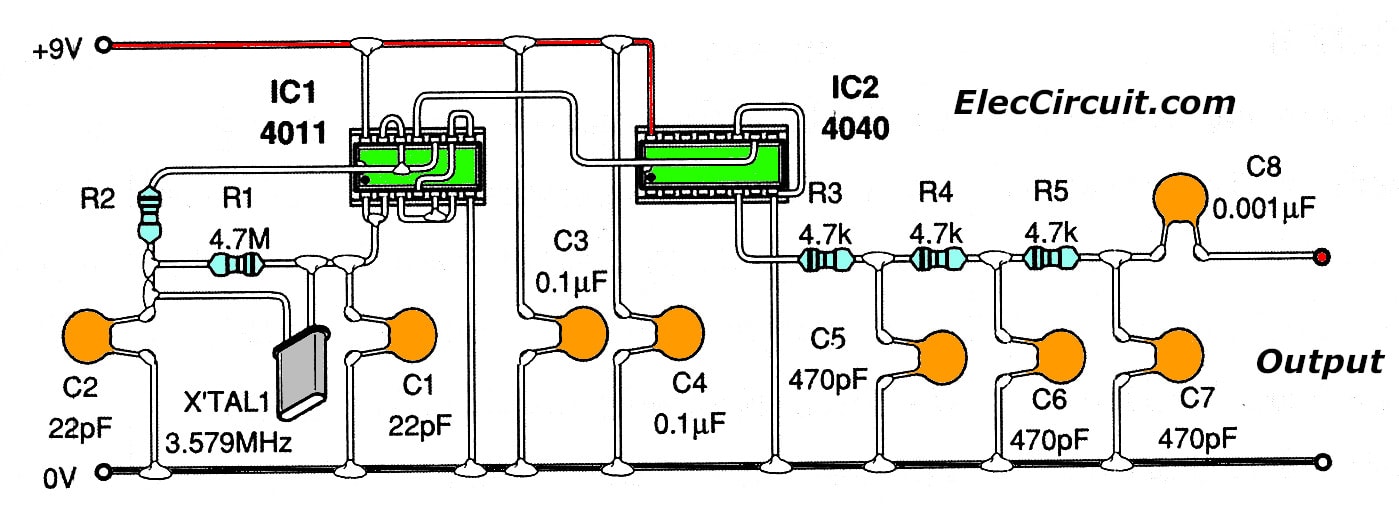
Figure 2 The wiring for this circuits
Learn: How to use 555 timer circuits
The components layout
Parts you will need
Resistors size ¼W +5%
R1: 4.7M
R2: 1.5K
R3-R5: 4.7K
Capacitors
C1, C2: 22pF 50V, Ceramic
C3, C4: 0.1uF 50V, Polyester
C5-C7: 470pF 50V, Ceramic
C8: 0.001uF (102) 50V, Polyester
Semiconductors
IC1: CD4011, Quad 2-Input NOR Buffered B Series Gate
IC2: CD4040, 12 Stage Binary Ripple Counter DIP-16
Others devices
XTAL1-crytals 3.579 MHz, 1 pcs.
Check out these related signal generator circuits, too:
- 0-100 MHz Multi-Function Digital Frequency Meter
- XR2206 Function Generator Circuit
- ICL8038 Mini Function Generator Circuit
GET UPDATE VIA EMAIL
I always try to make Electronics Learning Easy.
Related Posts

I love electronics. I have been learning about them through creating simple electronic circuits or small projects. And now I am also having my children do the same. Nevertheless, I hope you found the experiences we shared on this site useful and fulfilling.
Ӏ want to read more areas of it!
Please let me know if the pins of the 455 KHz oscillator are correct, i.e. CD 4011 and CD4040,
according to the schematic, because my assembled didi not work.
Thaks.
Edson Stedile
Hello Edson Stedile,
Thanks for your visit. I am very happy that you interested in this circuit.
First of all, With my sincerity. I have never built this circuit.
So, I cannot confirm it worked well.
But this circuit is interesting. I think you can try it. And modify and learn it very well.
Yes, I draw the circuit wrong at pins of 4011. Please try again.
If there is any progress. Please don’t forget to let me know.
I believe in you. You can fly.
Thanks again.
Apichet
Hello,
Thanks very much for your reply. In reality some pins of 4011 are wrong and I corrected them
when assembling the circuit.
I got stable 447.4 KHz in the output pin 6 of 4040. The filter seems not to be necessary.
The circuit works very well.
Regards,
Edson Stedile
Hi Edson Stedile,
Oh…It is great to hear that. Today, I am very happy.
You are good electronic person. If you have any things please do not wait. Please tell me.
Thanks again.
Apichet.
The circuit works well, but the low pass filter needed to be adjusted. A 3 stage filter nicely converts a square wave to a sine wave, but I calculated that the cut off frequency for the filter was only 72Khz! As I want it to pass RF I modified to 1.2k resistors and 220pf capacitors, and the cut off frequency rose to 602Khz. I have checked on my oscilloscope and get a great signal now.
Hello Ramon,
Thanks for your visit. You are smart. I want to see your experiment.
Happy New year.
Thanks
Apichet
Hi Apichet – I am not so smart! I am still learning and I am unsure of how to properly calculate the combined effect of 3 stages of low pass filters and my calculations were based on just the first stage – assuming that if my 465Khz gets through the first and higher harmonics blocked then the remaining two stages were simply for completing the square wave to sine wave conversion. However, my output was far better with the new values I used. Sadly I have taken the breadboard circuit apart now but have a photo of my final version output.
Hi Ramon,
Oh…Thanks for your reply. It makes me so happy in the morning.
You are smart! You learn electronics. I’m quite worried about Using text. Because my language basic is poor.
Thanks for the Google translate.
ํYour electronics learning is good. I want to learn the same from you. But I am 45 years. My brain is slower than before. and I have children. Every day is too busy.
Can I be friends with you? How old are you?
Have a great day.
Thanks a lot.
Apichet