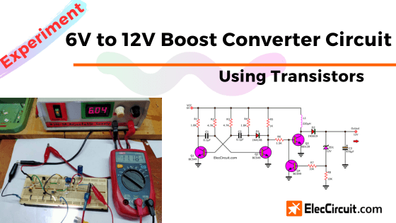
Today we are going to build a 6V to 12V boost converter circuit. Imagine you have a 6V battery, but you need to use it for a 12V load, like LEDs. Looking into your storage, there are only a transistor and simple parts with no IC.
What can you do?
Stop thinking of buying a new 12V battery when you could make use of the components you have to solve this problem.
Some people may call it a 6V DC to 12V DC step-up converter circuit. However, the output current is always lower than the input current.
6V to 12V boost converter using transistors
Here is a step-by-step breakdown of how it works
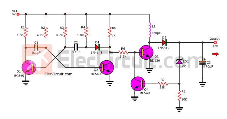
The first part of this circuit includes Q1, Q2, R1, R2, R3, R4, R5, D1, C1, and C2. Combined into an astable multivibrator that outputs a square waveform, that is, a positive pulse signal at high frequencies.
Then, the signal flows through R6 to limit a bias current flowing through the base of Q3. It causes Q3 to operate, so high current flows through L1; Q3 now acts like an on/off switch.
Read also: Transistor circuit works
This characteristic causes energy to accumulate in L1, and this energy will be released through D1 to rectify the current. Only the positive power is selected and stored in C1, which itself is an output. so causes the output voltage to gradually increase.
But when the output voltage increases beyond VZ of ZD1, which is 12V, current can flow through it and R7 into the base of Q4. This makes Q4 conduct current, like an on switch.
As a result, the current flowing through R6 is pulled to flow through pins C-E of Q4 all the way to the ground. Stopping Q3 from working. The voltage level at the output is reduced to approximately 6V because it is the current flowing through L1 and D1.
When the voltage level is lower like this, there is no current flowing through ZD1. The Q4 stops working. The current flowing through R6 flows through the base of Q3 again. The circuit works in these loops continuously, keeping the output voltage constant at 12V all the time.
With C3 acting as a smooth filter and storing electrical energy for the output’s load.
Other circuit: 12V to 6V converter
Parts you will need
0.25W Resistors, tolerance: 5%
R1, R4: 1.8K
R2, R3: 4.7K
R5: 1K
R6: 1.5K
R7: 33K
R8: 10K
C1, C2: 0.1µF 50V Ceramic or Mylar
C3: 470µF 25V Electrolytic
D1: 1N4148, 75V 150mA, Silicon Diode
D2: 1N5819, 40V 1A, Schottky Barrier Diode
ZD1: 12V 0.5W Zener Diode
Q1,Q2, Q4: BC549 or BC547, 0.4A 40V Transistors
Q3: BD139 or BD679 or equivalent, 80V 1.5A Transistor,
L1: 100µH to 220µH
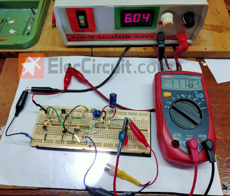
Experimental creation and testing
My daughter assembled the entire circuit on a breadboard and measured the output voltage. It was 11.6V, or about 12V. When a load was connected to this circuit, the output voltage level dropped.
In this circuit experiment, we can convert the voltage from 6V to 12V. And it is also great to learn the basics of a boost switching regulator circuit, or, as some call it, a step-up DC converter. It uses only basic electronics components, transistors, no ICs, familiar circuitry such as the astable multivibrator, and the principle of voltage regulation using the Zener diode.
And it is quite certain that it will have low efficiency. Because when used, only 4–5 transistors are used. Unlike ICs, which contain hundreds of transistors assembled to form an integrated circuit that works perfectly according to the manufacturer.
6V to 12V Step up converter circuit
No light! because of a low-voltage battery. How do you increase the voltage? You can do many ways. And, I recommend a simple step-up converter circuit using TDA2822. It can increase the input voltage of 3V-12V into 4.5V-22V at a max current of 300 mA. Imagine… With this circuit, you connect a 6V battery to a 12V lamp.
Oh…It is nice. But…Do you wonder why I use TDA2822? Often, TDA2822 is a small stereo amplifier well. Also, we can use it is the DC to DC voltage doubler circuit. They are a type of switching regulator circuit. But they are special patterns. There are IC, diodes, and capacitors only. Without a coil or transformer!
So, this circuit is easy and cheap. I like them. Or you too?
How does it work
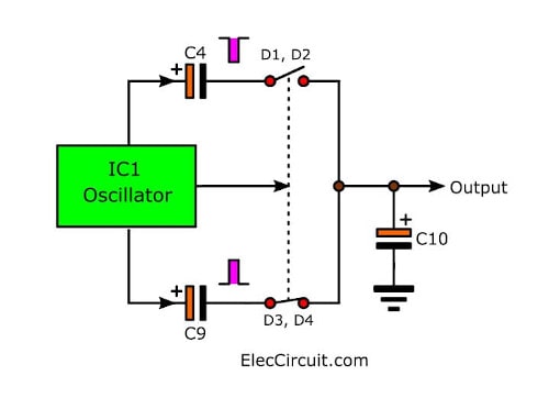
If you are not clear. See in the basic Block diagram again. The Step-up DC to DC converter is middle. It turns low voltage(input) to high voltage(output) for your load. And can increase the voltage about 2 times.
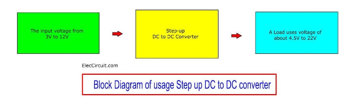
They are suitable for low voltage power supply. For example Rechargeable battery of radio communication, car battery, other small size battery, etc.
Recommended: What is switching power supply vs linear, how does it work?
A simple principle of the circuit
Here is a complete circuit of the simple DC to DC step-up converter project.
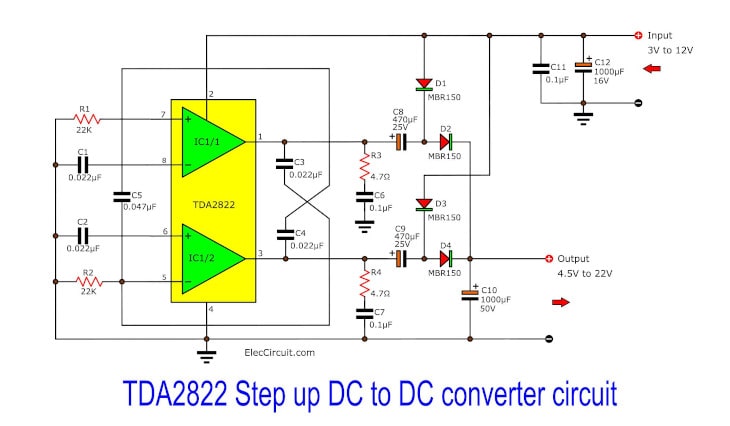
Here is a complete circuit of the simple DC to DC step-up converter project.
Look! The TDA2822 is striking with a new style.
You will see that inside IC has two op-amps. So, we set it in the astable multivibrator circuit. They make a pulse generator.
To control the on-off of four switching diodes (D1-D4) to charge and discharge at C10 to output.
We will have voltage is nearly two times of input voltage. Because of the voltage of C10.
Related: 555 DC to DC converter circuits
I feel that I explained to you not good enough.
Please keep seeing block diagram below.
I feel that I explained to you not good enough.
Please keep seeing block diagram below.
C10 is similar to a water tank. And, four diodes are a one-way valve.
They will work alternately. Because of different polarity.
Also: Simple 6V to 12V boost converter circuit using BD679 transistors
Suppose that the positive voltage of pulse comes. Cause D3 and D4 are ON. But D1 and D2 are OFF. The C10 will keep this voltage.
After that, the negative gets in, now D1 and D2 are ON. But D3 and D4 are OFF. So, C10 keep this voltage, too.
How it builds
This project, I bought the Kit from the store. So, It does not have the copper PCB layout. I cannot give you. I am sorry. But I think you are good. You can solder them on universal PCB.
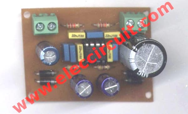
Below is a normal PCB. It is not clear.
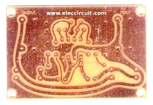
The Real PCB that I am sorry it is not clear.
Read next: USB 5V to 12V DC-DC Step-Up Converter circuit
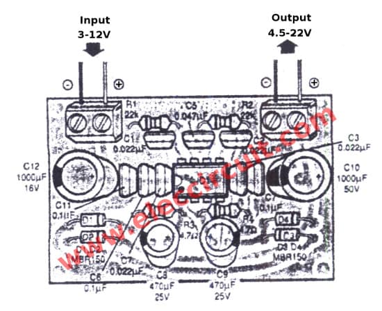
The components layout
We finish the DC to DC step-up converter
- 12 to 24V DC Converter
- DC Boost Converter circuit 3.3-5v to 12V
- Doubler voltage 12vdc to 24vdc with NE555
GET UPDATE VIA EMAIL
I always try to make Electronics Learning Easy.

I love electronics. I have been learning about them through creating simple electronic circuits or small projects. And now I am also having my children do the same. Nevertheless, I hope you found the experiences we shared on this site useful and fulfilling.
Sir what value is L1?
Mir gefällt das
Hello Dieter Jesse,
Thanks for your feedback.
Kontaktadresse : Dieter Jesse
Grudene 8e
58644 Iserlohn
Nordrein-Westfalen/ Sauerland
Germany
I speak not so good English
Ist auch ein deutschsprachiger Kollege bei Euch dabei ?
Hello dieter jesse,
Thanks for your visit to my site.
Also, my English is so poor. I have used Google Translate. It is really good for me.
No, We do not have who knows Germany. But I use google translate, I can understand what you said.
Thus, what do you want? Can we help? Do not wait, tell us, our friend.