Let’s learn a Voltage Multiplier circuit or Voltage Doubler circuits. Why? Imagine you need several kilovolts of high voltage. For usage such as lasers, produce fresh air, in industrial, anion generators, and various experiments as your imagination.
I learned these circuits with AC main 120V. In North America, most wall power is 120 V and a frequency of 60Hz. Other countries are similar to this principle.
The Voltage Multiplier circuits have many ways. But save way is using Diodes and Capacitors as Cascades circuit. This circuit is suitable for DC high voltage generator than a step-up transformer.
Sometimes we can use it in low voltage output. For example,
AC to DC converter 9VAC to 25V DC. etc.
Cascade voltage Doublers
First, we are going to learn a half-wave doublers circuit. Some called Cascade Doubler circuit.
Look:
There are 5 components in the circuit. Do you know how it works on each part? Even it is basic but some may forget.
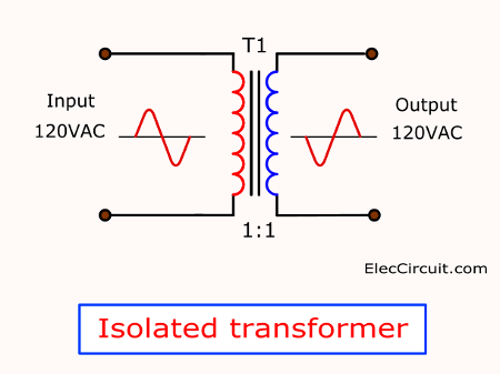
- We use T1-transformer to isolate different parts of the circuit and to provide protection from electrical shock.
- Use Diodes to set a direction of electricity.
- And, use capacitors to stores energy in short times just like a battery.
Here is the step-by-step process:
We suppose that both capacitors C1 and C2 are in starting mode to full discharge first.
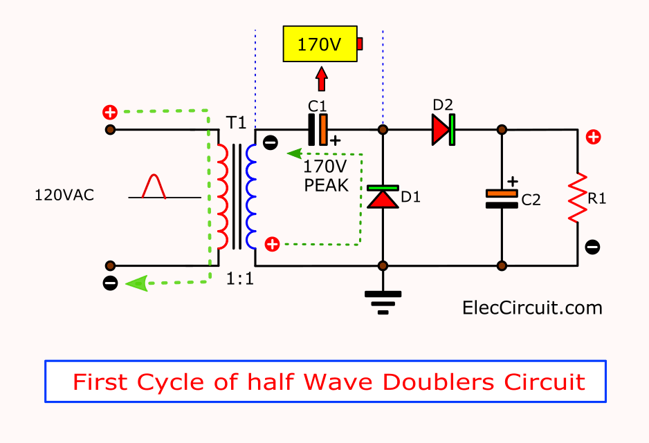
AC mains are sine waveform. The first step, in half of the cycle, is a positive voltage.
Then, D1 passes this to charge into C1. It stores this voltage about 170V Peak. We imagine it as one battery.
But D2 does not conduct current. Because it gets a reverses biased.
It makes C2 discharged through R1(Load).
As a principle, DC is 1.4 times of AC. So,
AC = 120V
DC = 1.4 x 120V = 170V (168V)
In contrast, when input is the second cycle, a negative voltage.
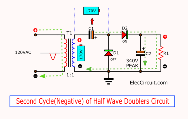
D1 stop to conduct current. But D2 conducts instead. And, makes C2 charges this voltage, too.
At R1 has voltage is 340V.
Because of this voltage Combined with C1 voltage as well. They are like two battery connected in parallel. So, the output voltage is 170V plus 170V equals 340 volts.
But these circuits not good at use with a high current of the load. Because they are the unregulated supply that has too many ripple noise.
Conventional voltage doubler circuit
What is more? We can use one diode and one capacitor is simplest voltage doubler circuit. Maybe you use it without knowing it.
Look:
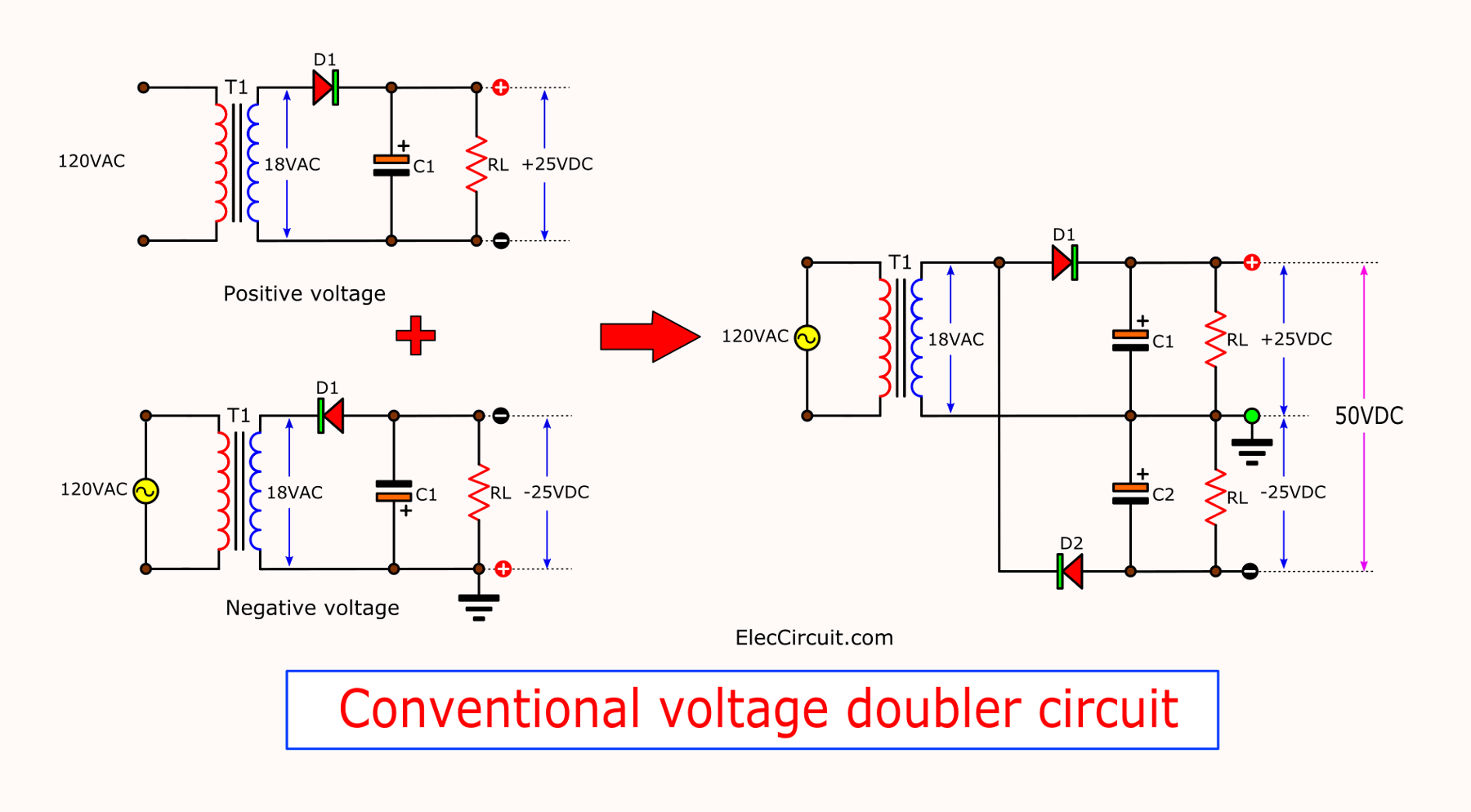
Three circuits are the unregulated power supply.
In fact, we not necessary to use a transformer. We use is isolated transistor and reduce AC voltage down to learn these circuit work.
Circuit A is Positive unregulated supply. To convert AC18V to +DC25V.
Circuit B is Negative voltage supply. It converts AC18V to -25V.
Both circuits are half-wave rectifiers. But have the different polarity of diodes and capacitors.
When we combine both circuits to one. By connecting input of diodes. We get output voltage is about 2 times like connecting 2 battery. It is a full-wave voltage doubler circuit.
Or it is 18VAC to 50V DC converter circuit.
We called Conventional form.
Are you understand?
The output ripple can be reduced by using more capacitances of C1 and C2.
Not only that.
Obviously, full-wave is better. Also, you can use bridge rectifier form for this.
Bridge doubler circuit
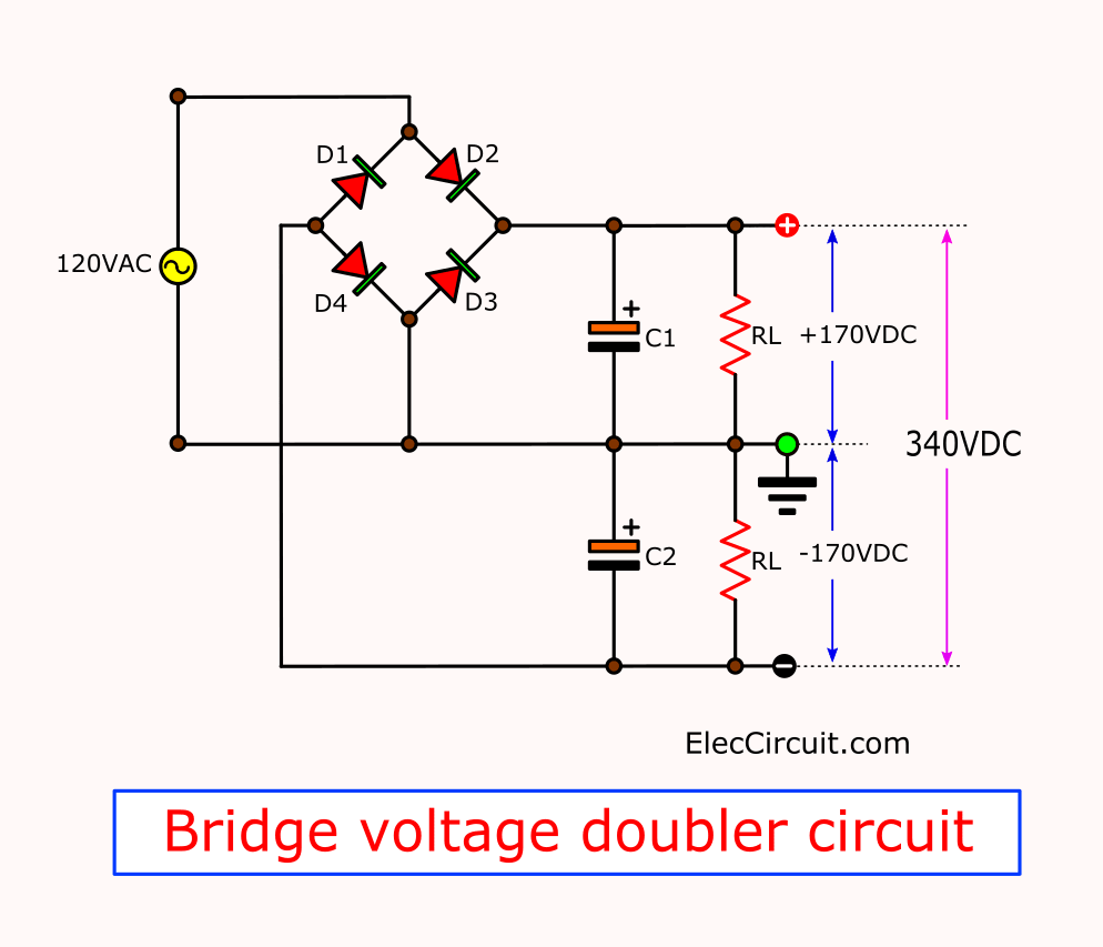
It is more efficient than conventional and cascade doublers. Because use 4-diodes as bridge rectifiers are available. It is easy to use.
For instance, in the circuit above, 120V to 340V bridge doubler circuit.
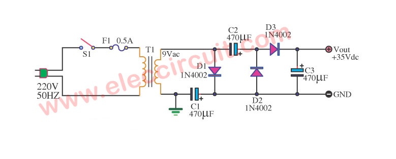
Simple AC to DC converter 9VAC to 35VDC
This again idea example ac to dc converter model to be simple. By modify 9VAC to 35VDC from when how many is see the circuit has already. Me uses base equipment only not? can enhance electricity pressure. See the detail in circuit picture.

I love electronics. I have been learning about them through creating simple electronic circuits or small projects. And now I am also having my children do the same. Nevertheless, I hope you found the experiences we shared on this site useful and fulfilling.
i want to create a ac-dc adapter with dc voltage regulating from 9-15V plz help. Can i use a regulator in the Simple AC to DC converter 9VAC to 35VDC on your site to get varying voltages??
plase I want 12VDC TO 19VDC 90W
Thanks
This is MY email :
[email protected]
thankyou
Hi karim,
I use this below.
Please look at here : https://www.eleccircuit.com/the-experience-to-buy-the-components-at-icstation-com/
12v ac to dc inveter
what is using ic
Can we regulated voltage from voltage doubler?
Hi
You should look at the circuit. DC2 DC converter is better. such as
https://www.eleccircuit.com/boost-converter-5v-to-12v/
https://www.eleccircuit.com/dc-converter-5-volt-to-12-volts-or-high-volt-than-12-volts/
https://www.eleccircuit.com/step-up-dc-converter-1-2v-to-5v-5v-for-micro-computer/
First of all, thank you for your sharing, on Cascade Doubler circuit I do not agree with your argument that when two voltage sources are connected in parallel, the voltage is not doubled but connected in series, in the positive half the voltage of the transformer winding in series with the capacitor C1 was previously charged, resulting in the voltage across the load doubling, and the role of the capacitor C2 is to filter. That is my deduction based on the knowledge learned.
explanation is precise easy to understand and to the point
and the diagram is also very clear
As-salam alaykum,
Thanks for your feedback.