Imagine you want to increase the DC voltage. For example, you have a voltage 5V to 12V, Or from 12V to 16V. We have many ways. In this article. Let’s try using the LM2577 IC. It is easier than other methods. It can greatly reduce your time. Of course, using IC is surely reliable, suitable for the present.
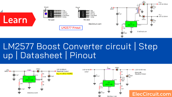
LM2577 Datasheet
The LM2577 or LM1577 is a simple Step-Up(boost), flyback, forward converter Switching Voltage Regulator.
Included on the chip is a 3 amp NPN switch and they have protection circuits, consisting of current and thermal limiting, and under-voltage lockout.
Read also: Step up converter circuit using TDA2822
Other detail within a 52 kHz stable-frequency oscillator that
no external components, a soft start mode to reduce running current during start-up, and current mode control for rejection of input voltage and output load transients.
Features
- Requires a few external components
- NPN output switches 3.0A, can stand-off 65V
- Wide input voltage range: 3.5V to 40V
- The current-mode operation for the improved transient response, line regulation, and current limit
- 52 kHz internal oscillator
- Soft-start function reduces in-rush current during start-up
- Output switch protected by current limit, under-voltage lockout, and thermal shutdown.
- Automatic overheat shutdown, automatic over-voltage shutdown, etc.
Typical Application
- Simple boost regulator
- Flyback and forward regulators
- Multiple-output regulator
Related: LM2596 circuit voltage regulator and datasheet
LM2577 pinout
Look at the LM2577 pinout on TO-220 (left) and TO-263 (right).
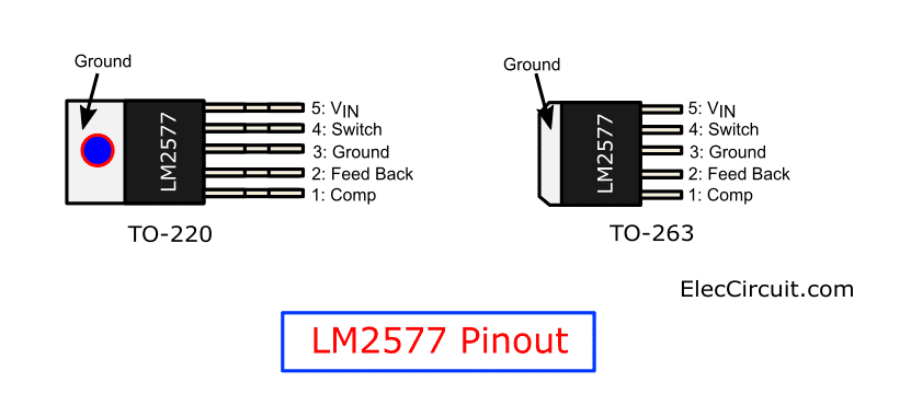
The output voltage. It can be determined by the IC.
- LM2577-12 for 12V output
- LM2577-15 for 15V output
- LM2577-ADJ for adjustable voltage 1.23VDC to 37VDC output.
Read also: How to use 7805 voltage regulator
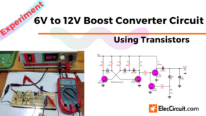
Test Basic LM2577 ADJ boost Converter circuit
Look at the circuit below.
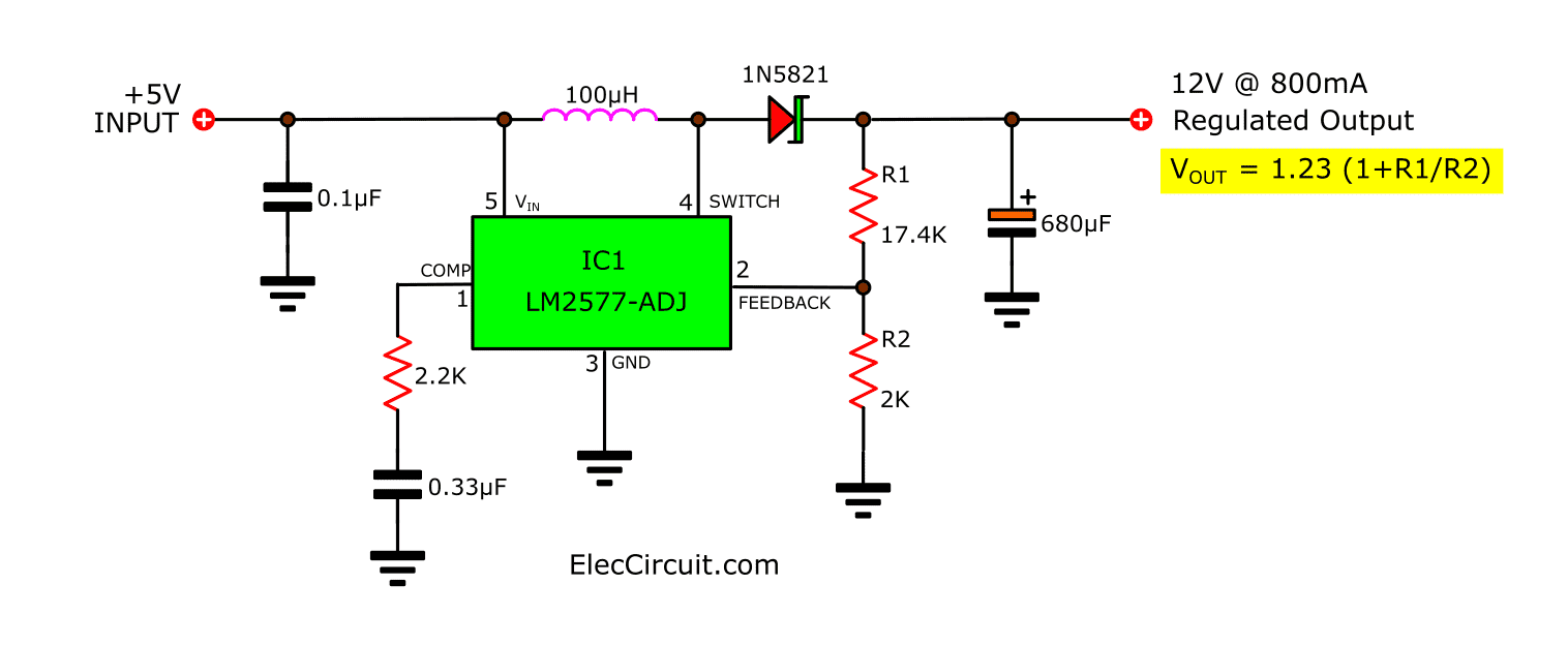
This circuit can increase the input voltage of 5VDC. It causes the output voltage to increase to 12V at 0.8A.
We use IC No: LM2577 ADJ. Therefore able to receive the input voltage 3.5V to 40V. And, The max output voltage of the circuit is 60VDC.
We can set the output voltage using R1 and R2.
Vout = 1.23 (1+R1/R2)
Recommended: USB 5V to 12V DC-DC Step-Up Converter circuit
Example LM2577 Circuits
These projects use a minimum number of external parts, these regulators are price reasonably good value., and made project easily.
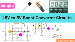
5V to 12V DC Converter step up Voltage Regulator
If you are looking an ICs for a DC to DC converter circuit. I highly recommend the LM2577 supply all of the power and control functions for step-up (boost), flyback, and forward converter switching regulators.
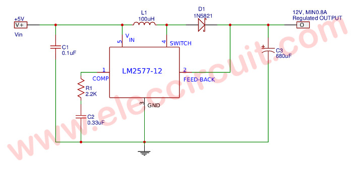
Look at the circuit diagram above. It is a simple 5V to 12V DC converter.
The output voltage typical: Wide input voltage 3.5Vdc to 40Vdc.
Component list
- IC1: LM2577-12
- 2.2k 0.5W resistor
- 0.1uF capacitor
- 0.33uF capacitor
- 680uF 50V electrolytic capacitor
- 1N5822 high-speed Schottky diode (3A)
- Wire coil inductor, 100uH
Note: If use LM2577-ADJ. use 20k multi-turn variable resistor, set to ratio to R2=2k, R1=18k. And This setting for voltage output of 12V before soldering.
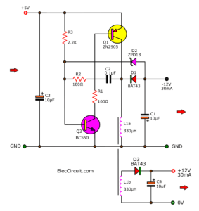
Read next: 5V to 12V boost converter circuit or higher using transistor
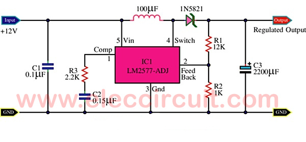
Adjustable Step-up Boost Converter using LM2577-ADJ
With this circuit below, you can set the output voltage of 1.23V to 60V.

Parts you will need
- IC1: LM2577-ADJ
- C1: 0.18uF 63V Ceramic or MKT capacitor
- C2: 0.33uF 50V Ceramic
- C3: 1,000uF 80V Electrolytic capacitor
- R1: 1K 1W Resistor
- R2,R3: 2.2K 0.5W Resistor
- D1: 1N5821 high-speed Schottky diode (3A)
- L1: Wire coil inductor, 100uH
12V to 16V Step-up DC to DC Converter using LM2577
It is similar to the circuit above. The circuit is a boost step-up regulator based around an LM2577-ADJ voltage regulator chip and a few other components.
Both Resistors R1 and R2 set the regulated output voltage.
A switch inside the voltage regulator closes between pins 4 and 3, causing current to flow through the inductor to ground.
When the switch is released a few microseconds later, a back-EMF ‘kick’ is produced by the inductor.
This result is a positive pulse with respect to the input voltage. This pulse charges the output capacitor via the Schottky diode-D1, which tends towards an equilibrium voltage.
The switch continues to oscillate, the diode preventing the switch from shorting the output capacitor during the ‘on’ phase.
The output voltage is monitored via the voltage divider R1/R2, causing the duty cycle of the switch oscillator to be continuously regulated in order to maintain a constant output voltage under varying loads.
3.7V 5V to +15V -15V DC-DC Converter Step-up Boost Dual Voltage
If you are building a large digital circuit You only provide 5V power supply. But by chance, you have to use a good quality preamplifier with the tone control circuit. It requires DC regulated power supply, 15V, -15V and GND.
Look at the circuit diagram below. It might be a good solution.
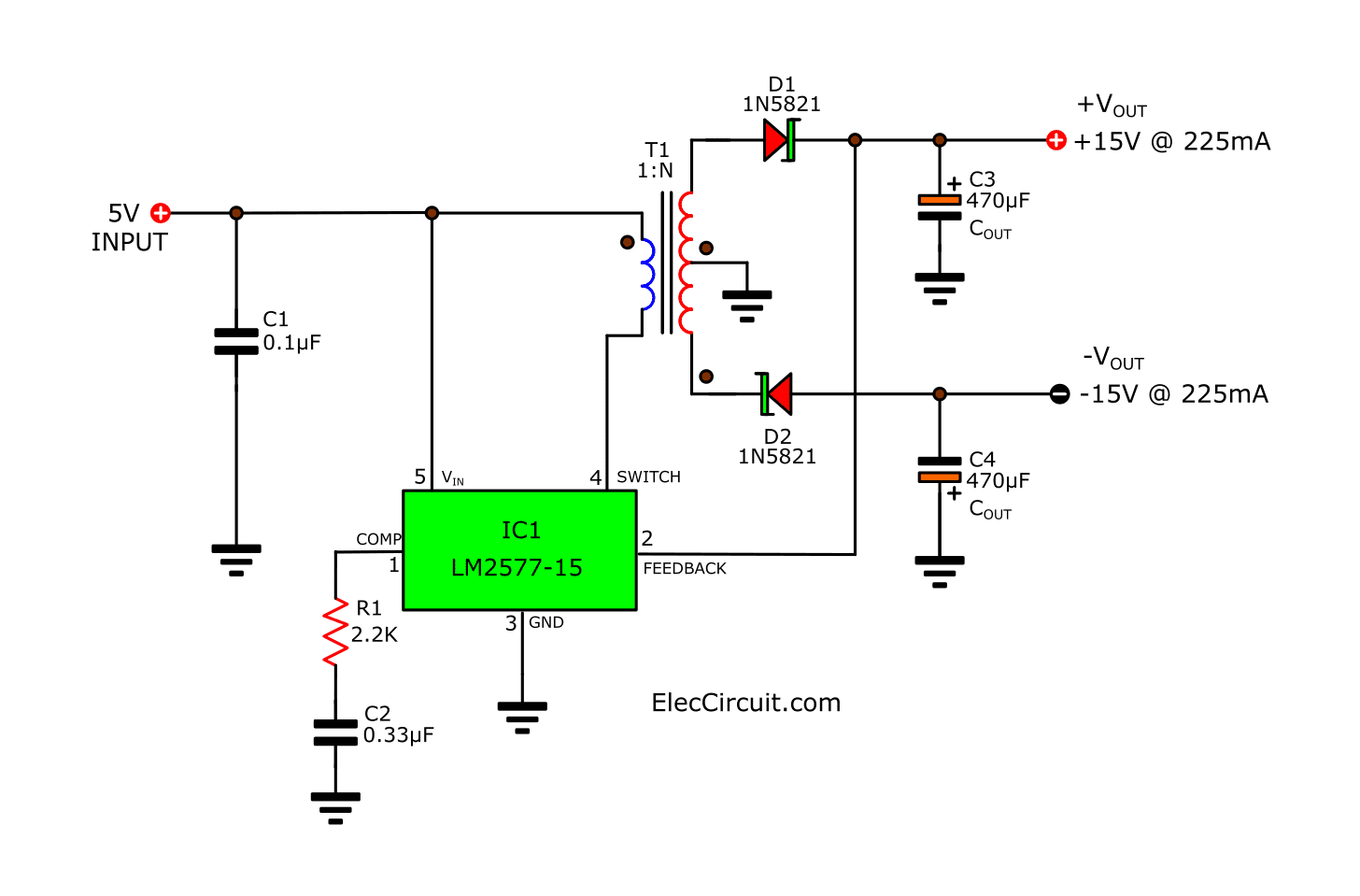
This is the flyback Regulator Easily Provides Dual outputs.
A Flyback regulator can produce single or multiple outputs
voltages that are lower or greater than the input supply voltage.
In the circuit shows the LM1577/LM2577 used as a flyback regulator with positive and negative regulated outputs.
Its operation is similar to a step-up regulator, except the output switch controls the primary current of a flyback transformer.
Note that the primary and secondary windings are out of phase, so no current flows through secondary when current flows through the primary.
This allows the primary to charge up the transformer core when the switch is on.
When the switch turns off, the core discharges by sending current through the secondary, and this produces a voltage at the outputs.
The output voltages are controlled by adjusting the
peak primary current, as described in the step-up regulator
section.
Here are a few related posts you may find helpful, too:
- Simple 12V to 24V step up converter circuit using TDA2004
- 7 ideas of 555 DC boost converter circuit
- DC Boost Converter circuit 3-5V to 12V-13.8V
Related Posts

I love electronics. I have been learning about them through creating simple electronic circuits or small projects. And now I am also having my children do the same. Nevertheless, I hope you found the experiences we shared on this site useful and fulfilling.
Real good and helpful
Hi, MUSOKE THOMAS.
You welcome.
I am glad to it was helpful for you.
troppo basso di corrente di uscita.
a serve ma con 3/4A di uscita
what if 1amp is need, input can be enhanced to 9v?
what if 9v,1amp out put is required?
Im confused about the inductor. Which inductor should i use? I know its the 100uH type but there are lots of variations of inductor.
Where I ccann find 20k multi-turn variable resistor,2k and 8k,
Is it the same like regular resistors?
I’m. New to this I wanna build that but I went to radioshack they didn’t have that or the LM2577
If you need more than 1amp up to 5amp, there are a simple module SMR8805 8809 8812 etc, its abput the same size as 78xx, high efficiency and cost only about $3 ready to use,
elkalan.blogspot.com
buenas tardes nesesito saver como bajar 24 dc A 12DC GRASIAS
Hy, I need to step-up from 3.7 (1LiPO cell) to around 11V to power up an LCD backlight from an old tablet pc and use it on other projects.
what parts need to be changed or I can use this circuit as it is?
If I would like to change the inductor 100uH for another of 220uH, what would happen? Is there any problem with the circuit?
Hi, Noel
Thanks for your feedback.
I’m sorry, this not tested by us.
But I think, …
Its frequency and current maybe changed.
If you tested then can see happen it, please share to us,
Thaks a lot.
Hi… the output voltage is constant 12v dc or not because i need costant supply of 12 v and the current is in mA or nt for this circuit…pls rep..
Hi… my input voltage is 20-22v dc this circuit can give me constant 12 v supply….
Hi Prashant sawant,
Thanks for your feedbacks.
Please look at : https://www.eleccircuit.com/tag/12v-power-supply-circuits/
It has many circuit to use.
https://www.eleccircuit.com/regulator-5v6v9v12v-1a-by-ic-7805780678097812/
https://www.eleccircuit.com/simple-regulator-by-transistor-c1061/
Hello,
I am looking for a circuit to convert 5 VDC to 12 VDC @ 1.6 Amps. All the circuits I’ve found are under 1 amp output. Can you offer assistance?
Thanks,
David
Hello,
May I use your circuitry for a school project?
Best Regards,
Thomas
Hello. May I use your circuitry for a school project? Thank you in advance.
Do this ic LM2577 require constant input to give 12v? I mean can i connect this circuit to variable speed dc motor (acting as a generator here) and obtain12 v from it?
sir, can i varying the 12v dc?
Write a comment…pls how can I build a 19V 5A adjustable DC to dc boost comverter from 5v – 12v input v. range
Thanks..
We do have a 12V to 19V 5A DC to DC converter circuit in our circuit storage. But explaining it now might be difficult and troublesome because of the circuit is untested and has high detail intensity. But we love a power supply, in the future, we will bring it up again.
Please stay tuned.