If you are looking for a power amplifier for listening in a small house. This may be a good choice for you. It is a TDA2030 transistor amplifier.
Why is good? Because of the higher power than a mini amplifier. With an output power of 20W at 8Ω or 30W at the 4Ω speaker. Even max to 40w with higher power supply.
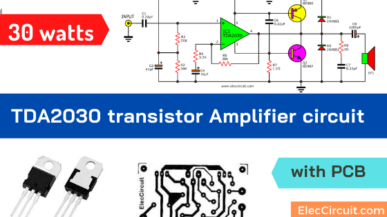
In normally TDA2030 delivers the power of 15W max. But this circuit we use two transistors to increase more output power.
Although, it is great. But do not worry. It still is easy to build, without any adjustment.
The working principle
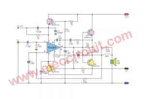
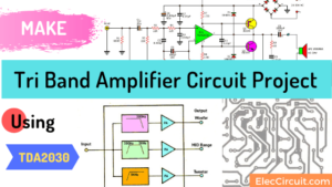
As shown in the figure the circuit, you see three main components. They are like three soldiers, TDA2030 and two transistors (BD908, BD907 or TIP41, TIP42 or 2SC1061, 2SA761). Their helping to increase the signal up there.
Others components are useful as well. However, I will explain them to you learn as follows.
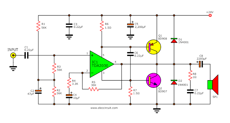
Figure 1. TDA2030 transistor amplifier circuit 30 watts output
When we enter the power supply and sound signals into this circuit. The capacitor C1 will prevent DC voltage through input. So, the sound signals can get into the pin 1 of IC1 easily.
Also, this circuit uses a single power supply that has two terminals are positive and Ground(negative).
So, we need to connect two resistor R1, R2, and C2 to divide the voltage by half. And, the R3 matches the input IC1.
In the circuit, the gain of IC1 is set to 14. Because it is a non-inverting amplifier pattern there.
Transistors boost up IC amplifier
The output signal flows out of pin 4. But it still is low. We need helping with the transistors. Both transistor Q1 and Q2 increase more power-up.
How do they work? Resistor-R6 passes the current to supply IC1 of the positive terminal. Also, Resistor R7 passes the current to IC1 of the negative terminal.
When the many currents flow through R6 and R7. Then, the voltage drop across them exceeds 0.6V. Which is bias voltage to Q1 and Q2.
So, they help to pass more current from the supply to output.
After that, the higher output signal flows the loudspeaker through C8.
While this circuit can protect the loss of high frequency that output to the loudspeaker by R8 and C7.
Also, both diodes D1 and D2 are used to prevent the return voltage from the speaker not to interfere with the IC1, Q1, and Q2.
If none of these two diodes may damage the device, including money in your pocket, too.
And, both filter capacitor the C7 and C8 smooth the power again before it is provided to the circuit there.
You may also like these:
How to build and setting
The Familiar thing in building the project is to make PCB (printed circuit boards) as the image below.
Click to view full size image.
To make PCB
Print it on 300 dpi
And, buy electronic components from stores list below.
When you finish the PCB and list. Next, you solder them on PCB
as shown in Figure 3
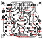
Components layout of TDA2030 transistor amplifier project
I believe you know the process of creating a good project.
You should Solder the components onto PCB, the low end to high end will be a beautiful view.
Make sure the device is a correct terminal before soldering.
This project uses IC1, Q1 and Q2 should use the big size heat sink to install them together as shown in figure 2.
Shopping lists
R1,R2,R3: 56K, 0.25W Resistor
R4: 3.3K(3K3), 0.25W Resistor
R5: 30K, 0.25W Resistor
R6,R7: 1.5Ω, 0.5W Resistor
R8: 1Ω , 0.5W Resistor
C1,C3,C6,C7: 0.22uF(224) 63V, Polyester Capacitor
Electrolytic Capacitors
C2: 47μF 25V
C4: 10μF 25V
C5,C8: 2,200uF 50V
Semiconductor devices.
D1-D2: 1N4001 or 1N4002
Q1: PNP transistor BD908 or 2SA671 or TIP42 or TIP32
Q2: NPN Transistor BD907 or 2SC1061 or TIP41 or TIP31
IC1: TDA2030
Sheets of mica, Cooling pad (Heat sink)
Other: TDA2030 transistor amplifier circuit
How to use
First, need to use the DC power supply of 24V to 30V of 1A for MONO.
Then take the audio source as the tuner, cassette or a CD player to test it.
Finally, Connect a 20W 8Ω the loudspeakers to the output.
For those who want to listen in stereo, you need to build up to two circuits. And change the power supply of 2 A. It can be used.
Look at Simple 24V 2A Unregulated Power supply circuit below.
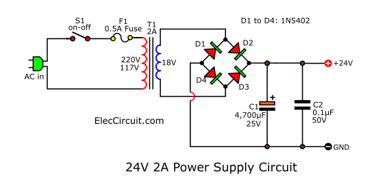
You should use 2A transformer, C1-4,700uF 50V, and D1 to D4 are 1N5402 diodes.
If you want a good circuit you may use 24V 2A regulated power supply. It is great.
Now, it is time to listen to a crystal clear sound from your created yourself.
…
Download This
All full-size images of this post as PDF in the Ebook. Thanks, support me. 🙂
Not only that look at: These circuits
GET UPDATE VIA EMAIL
I always try to make Electronics Learning Easy.

I love electronics. I have been learning about them through creating simple electronic circuits or small projects. And now I am also having my children do the same. Nevertheless, I hope you found the experiences we shared on this site useful and fulfilling.
hello the actual size of PCB ?
Hi lvan
Thanks for your visit.
Please Make it on 300dpi printer size setting. It is about 2.2 inches
Have a good day.
מחפס לירכוש מעגל אלקטרוני להגברת רמקולים למחשב שיהיה בה מעגל טרבל בס וליום 20wtקיט להרכבה עצמית
Hi oshe,
Thanks for your visit.
I cannot you Google translate for your text. Please type in English.
Thanks
Apichet
i did this one with a input voltage of 30v but i think the ampere is low (500mA) and the output is getting distortion and i have a 50w speaker 4ohm… what to do ??? i have no idea !!.
– Forget this schematics. If you won cheep and easy build nice amplifier use TDA7294 witch is 90W into 8ohm +/- 30V power supply. I already build one. If you need correct schematic and PCB just e-mail me I’ll send you pictures and all you need.
– If you won bridge schematic for TDA2030 (35W max into 8 ohm) e-mail me and I’ll send you all you need. [email protected]
Hi yes I am interested in this schematic for TDA7294 please send
Where C5 in PCB ?
c5 look missing in the pcb
I BUILT THIS AMP WITH TIP41/42 TRANSISTORS SINCE THE BD COUNTERPART IS NOT AVAIL IN COLOMBO.BUT THE OUTPUT IS ONLY 13WATTS. EVERY THING IS DONE AS PER CIRCUIT. VOLTAGE SUPPLIED IS 35VOLTS WITH 4AMPS IN STORE.IAM NOT GETTING .6V ACROSS THE TWO 1.5OHMS RESISTORS TO FIRE THE TWO OUTPUT TRANSISTORS,ONLY .4 V. PLS ADV ME WHAT THE PROBLEM COULD BE.MANT TKS
I finish my amplifier few day’s ago. Everything working fine , sounds very good , low heat disipation and low distorsion. Using TDA2030A with TIP41C and TIP42C. Transformer is 4A / 24V AC , so 24V x 1.3 = 31V DC and 6800 mF cap. Tested on 4 ohms speaker / 50 W. Great sound ! For any help and pictures: [email protected]
hey man this is awesome, it has no distortions. Works like magic!! thanks
i buit this circuit n i faced a new kind of problem.
i made 2 channels with the same schematic except i used 2.2ohm /0.5W instead of the 1.50hm.
One of the channel works quite well…very good sound indeed!!!..but for the other channel 2.2ohm resistor from pin 5 is getting fried when i powering the circuit with 24volts 1amp supply with filter cap of 4700uf.
Plz help me out…m in a serious mess…
Heres my email:[email protected]
for any kinda help.
Thanks to all in advance.
i built this amp but getting distortion any one with a better idea should kindly mail me at
[email protected]
Fiz um amplificador como o esquema. Más quando alimento ele e ponho no volume maximo, pega fogo no resistor de 1,5ohm, e os dois transistores queimam. Usei TIP31/32.
Estou alimentando o circuito com +-35v 2a. Seria o problema a tensão de alimentação acima de 30v?
I’ve success made this TDA + Power Transistor curcuit.I use TDA2050 + TIP3055/TIP2955.Single supply setup at 48VDC/3A for the curcuit.I use 2pcs 24VDC/3A + 24VDC/3A ITE adaptor in series.
Base on standard TDA2050 single supply schematic.Added 10 Ohm 2Watts X 6pcs on parallel for (1.66 Ohm).All 12pcs 10 Ohm 2 Watt for both ground and positif rail.Output capasitor i use 50v/2200uF X 2pcs also on parallel to get 4400uF for speaker out.
Sound awesome the bass impact with woofer 6.5″ x 2 pcs on series to get 8 Ohm config.I use 2 pcs altec lansing VS4621 woofer.Make my glass windows in my room rattt…krrr.rrr….krrrr….shaking on 70% > volume up.!! 😀
Can you give me the schematic please , My email : [email protected]
On TDA2030 + power transistor above..What does C6 do to this curcuit?Im noob any explaination?my power resistor (R6) on PNP got overheat by adding C6.So i remove it then it balance on both power resistor (R6) and (R7).Im bit comfuse on this,Do i make anywrong connection?I follow the schematic above..C6 make problem on my curcuit,why?
The circuit is great, but rather scared about the Two
1.5 ohm resistors. I have one ohm – 1 watt. Transistors shouldn’t blow!
I built this Amplifier on breadboard it works fine on 8 ohm speaker, good clear sound, I used 2watts 1.5 ohm resistors, at 12v supply the IC did not show sign of becoming hot, I replaced the 0.22uf Polyester capacitor with 100nf ceramic it perform well, the circuit may need volume control to add to the schematic.
Hello, Ali
It is great. I am happy to you finish this circuit. It is good that you experiment and observe it.
This circuit is suitable for 24V supply. If you change the input capacitor it may change impedance input and Changes in frequency response. Read here: https://www.eleccircuit.com/uses-of-capacitors-rc-time-constant-coupling/
Have a nice day.
This circuit works well. it’s so nice!
Hello Tome,
Thanks for your feedback.