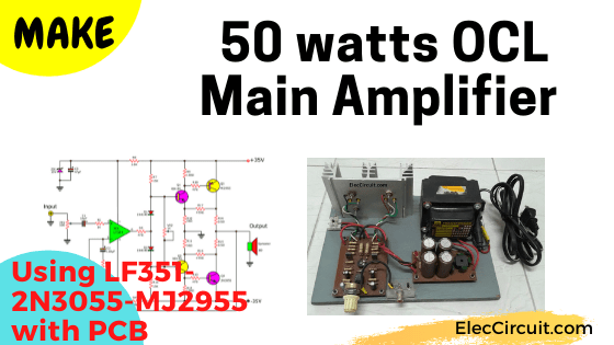
If you want a 50W OCL main amplifier circuit, high quality and save money. I recommend this circuit.
You can use it to amplify the normal sound in the home. At the level of pleasant sound power. It was the first amplifier circuit that I created. Also, we will often see this circuit in a generally affordable amplifier.
Why?
Because it has fewer components others circuits. It consists of transistors-2N3055-MJ2955, a low noise IC-LF351, a few parts. And, you can buy them easily.
If compare it at the same volume level is cheaper than other circuits.
Of course, everything has its disadvantages.
This circuit also has a disadvantage, it is an OCL amplifier. Someone who is interested in an audio system would know that if something goes wrong. It may easily cause the speaker to be broken.
However, we can reduce the problem as well. Add the speaker protection circuit.
And it has likely an interference easily as well. Which we also reduce this problem, choose IC with low noise.
This circuit is suitable for Experienced people, people who have already built other small amplifiers. However, if you are a beginner. We will build it meticulously and have a process. Yes, you can do it.
Main power amplifier working
Designers set this circuit in “Direct Coupling All Complementary IC Drive”. The heart of the circuit is IC1(LF351). It is the differential amplifier pre-driver circuit.
Note:
I chose LF351. Because of the lower noise reduction circuit. Also, high-frequency response than IC741. While you may use a TL071 or NE5534N is good quality as well.
The output signal of IC1 flows through two 1N4148 diodes D1 and D2 to the transistor drivers Q1(BD139), Q2(BD140).
Then, these current come to two main transistor output Q3 (MJ2955), Q4(2N3055).
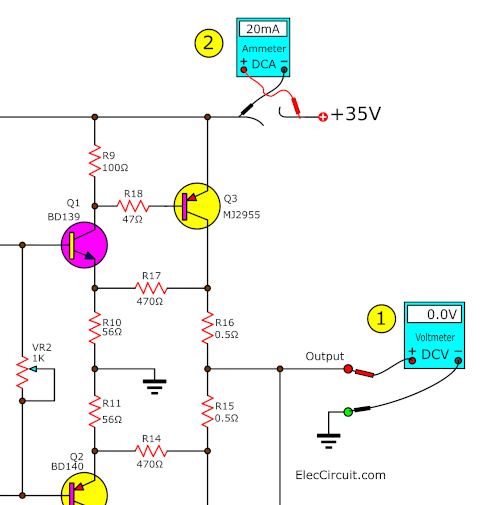
The small Potentiometer VR2-1K is adjusted to the idle current of this amplifier circuit. This circuit is so easy to adjust.
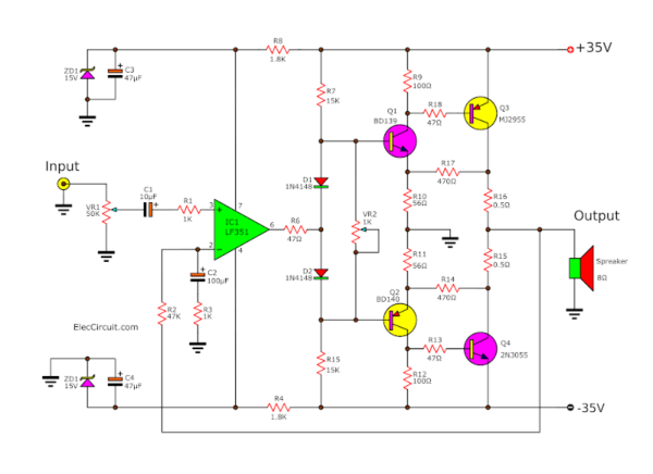
If you do not have an ammeter, you do not need to measure the IDLE current. You just adjust the VR2 in the middle only (very simple!)
35V Dual DC power supply
This main amplifier requires an unregulated power supply circuit that can supply sufficient electrical power.
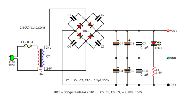
C1, C2, C3, C4 eliminates a high-frequency noise signal that may occur while BD1(Bridge Diode) is operating.
LED1 shows power on. The R1 limits a safe current for LED1.
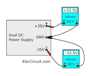
This is DC Dual power supply, +35V GND -35V 3A for the MONO system.
But if stereo system, We need a power supply circuit that can supply twice the current.
- Change transformer to 5A
- Add more filter capacitors(C5, C6, C8, C9) 4,700uF to reduce a ripple voltage (noises or Hum…).
How to Build
First of all, get the components as electronic parts below.
The Electronic parts
I think this kind of circuit High flexibility. Some people may use different components.
The Main Amplifier
IC1: LF351, TL071, LM741 op-amp; See text below
Q1: BD139 or 2N3053(TO-39)
Q2: BD140 or 2N4037(TO-39)
Q3: 2N3055 or TIP3055
Q4: MJ2955 or TIP2955
ZD1,ZD2: 15V 0.5W (1N5245) Zener diode
VR1: 50K (A) Potentiometer
VR2: 1K pot
C1,C9: 10uF 16V Electrolytic capacitors
C3,C4: 47uF 25V Electrolytic capacitors
C2: 100uF 16V Electrolytic capacitors
D1,D2: 1N4148 Diode
PCB, 8 pin DIP IC Sockets, and more.
The Power supply
BD1: 6A 100V Bridge Diode
C5, C6, C8, C9: 2,200uF 50V Electrolytic Capacitors
C1, to C4, C7, C10: 0.1uF 100V Ceramic or Mylar Capacitors
T1: 24V CT 24V, 3A secondary transformer
R1: 6.8K 0.5W resistor
LED1: LED any color
F1: 0.5A Fuse
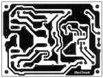
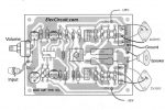
Then, get the Actual-size of Single-sided Copper PCB layout and PCB layout. See below.
- Check the completed PCB, Is it defective, short circuit?
- Before assembling an electronic circuit, be careful with polarized devices. We only need to connect them correctly.
Download This
All full-size images of this post are in this Ebook: Elec Circuit vol. 2 below. Please support me. 🙂
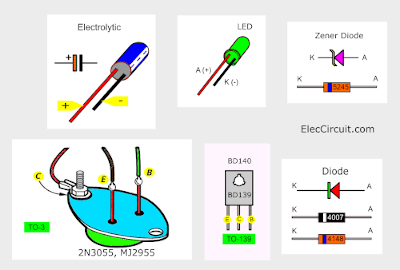
While working, the power output of the transistor is very hot. So we have to mount it on the heatsink. And we should have the correct mounting method. Because of its structure, pin C is connected to the body.
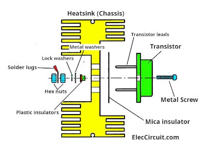
See the pattern below for the correct mounting. After that check that does not shorted-circuit between each leads C, B, E, and the Heatsink, with using Digital Multimeter(DMM) to CONTINUITY.
You must sure that:
1. The screws tight, not fell, they lose easily.
2. Do not the short circuit between the collector Pin (transistor body) and heat sink, Due to the installation of mica insulation is not well.
Step by Step making
- Assemble the power supply circuit first. Measure the output voltage level with a Digital multimeter. Set to dial of the Digital Multimeter(DMM) to DCV. Then, touch the end of both probes between +V and GND and -V. It is +33.9V (approx 35V).
- Assemble the main amplifier circuit. Except, do not put IC1(LF351) and power output transistors Q3(2N3055) and Q4(MJ2955).
Why does not put the transistors? Because while the transistors are working. They will have a high current. If there is an error. It has very damaged the circuit. So we have to check it thoroughly first. - Check the circuit again.
- Connect the power supply to the circuit. And turn on it.
- Use a voltmeter to measure the voltage at ZD1 and ZD2. Each Zener diode should read at 15V. Because the op-amp IC1 requires this regulated voltage supply. (+15V GND -15V)
- Then, turn off the circuit. Put IC1 on the socket 8 DIP. Rotate, the VR1 (Volume) to a minimum.
- Next, turn on the circuit. And, Measure voltage between the output speaker and ground point. We should read the meter is zero volts. Or error must not exceed 0.5V.
- We need to figure out why the voltage is not zero. And solve it. Please check again.
- Then, Put these output transistors into this circuit. The voltage must be OV the same. If non-zero, indicating that the bad output transistors.
- Then, adjust Idle current with rotating VR2. Look at the block diagram above. Start with set VR2 in middle. Measure the current of the circuit with the Ammeter. Rotate VR2 until reading the meter at 20mA (approx).
- Now you are done with the customization process. Connect speakers and enter signals to the input of this amplifier circuit.
Mistake and possible causes
Sometimes the circuit may not work as expected. You can consider these reasons.
If measuring the voltage is not zero.
1. It is a positive. The mistake point may be caused by:
- Check IC1, it is an error.
- Transistors – Q1 and Q3 may be broken in an internal short circuit.
- Transistors – Q2 and Q4 may be broken in open-circuit, not runs.
2. It is a negative. Check these:
- Check IC1
- Transistors – Q2 and Q4 may be broken in an internal short circuit.
- Transistors – Q1 and Q3 may be broken in an open circuit.
3. It is zero. But no sound. Check R15, R16 They may lose.
4. The sound is not clear. The sound has noise.
- Check the B-E extension wires of the power output Transistors. There may be a problem.
- Bad quality IC
- Oscillation or noise within the circuit.
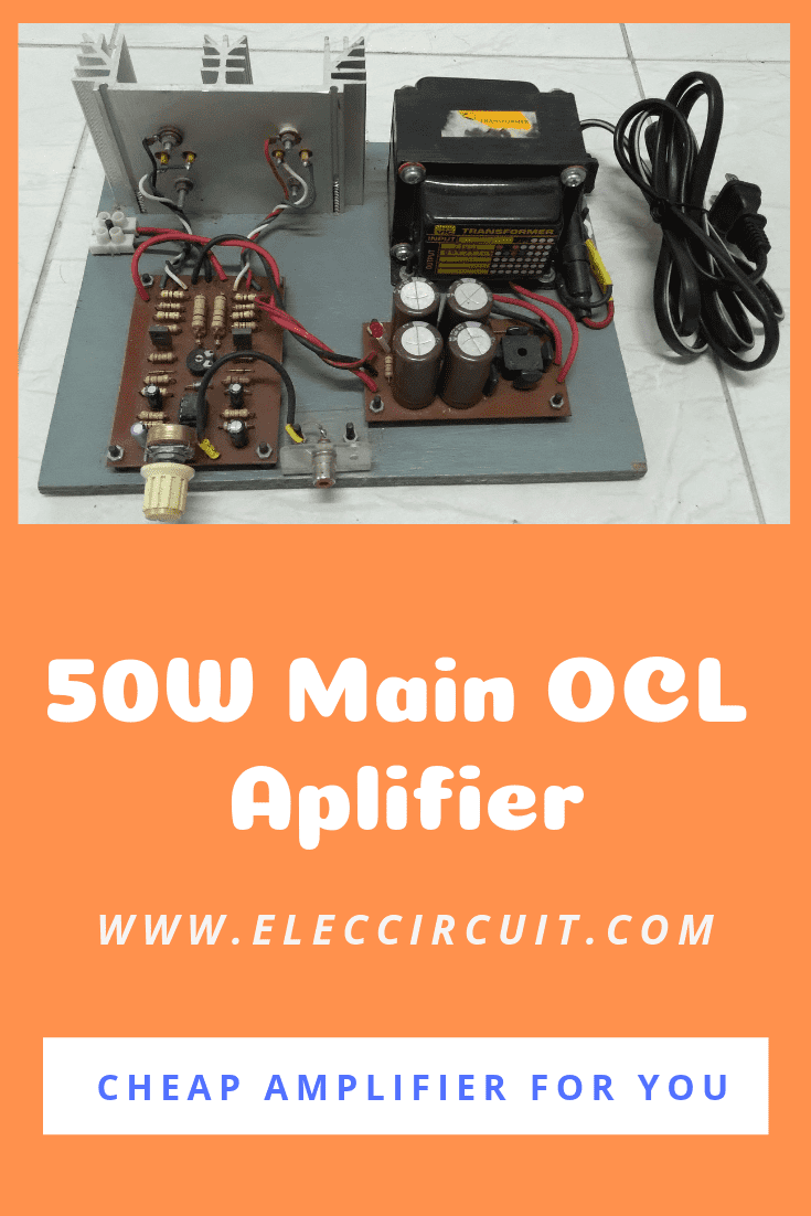
See the prototype of 50W amplifier circuit.
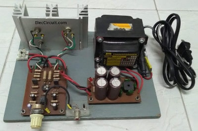
Front
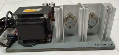
Back of the project
Read also:
- TDA2050 amplifier stereo 35W-75W
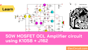
- 50W MOSFET amplifier circuit OCL
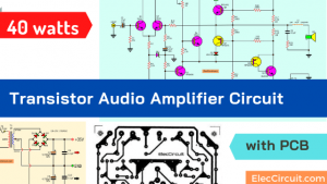
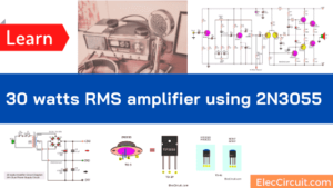
- 2N3055 Amplifier Circuit with PCB | 60W
Change for the better
- IC-LM741 is a normal Op-amp IC. It is cheap and popular. But if you use LF351, low-cost high-speed JFET input operational amplifier. It works well.
- You may use TIP3055 and TIP2955 instead of 2N3055 and MJ2955. Because they are small size but have high power.
- Change the voltage of the secondary transformer to 27V CT 27V 3A. It makes the voltage of the power supply up to 38.17V. So, the power of the amplifier also up. But it shouldn’t add too much voltage. Because power transistors can tolerate a voltage of no more than 60V. It may cause oscillated noise more easily.
Remember
This circuit is an OCL amplifier. So, you should a Speaker protector circuit, too.
Besides this, we introduce these easy projects. Sometimes, you may like them.
GET UPDATE VIA EMAIL
I always try to make Electronics Learning Easy.
Related Posts

I love electronics. I have been learning about them through creating simple electronic circuits or small projects. And now I am also having my children do the same. Nevertheless, I hope you found the experiences we shared on this site useful and fulfilling.
I require Simple universal audio music system of 6volt
You can choose them on https://www.eleccircuit.com/tag/small-audio-amplifiers/
To whom it may concern,
I am working in a powder coating plant as a manager. We have electrostatic machines that uses +/- 70 – 80 kV and only micro amps to charge the powder.
I have several diagrams of how to build a voltage multiplier but I need a little more help.
If the input voltage is max 16 volt AC but can be varied to less with a pot to approximately 50% to produce 35-40kV output. The transformer circuit also goes through a TIP3055 transistor and have 2 x 5W 220ohm resistors. I do not have a complete diagram as yet due to time limitations.
Can you think about this and assist in designing a proper circuit with components so that I can build these units for my self.
The machines we have were Staticote machines and I don’t get repair assistance without being severely overcharged.
Thank you for your time. I hope you can assist me in this regard.
Christo Smit
Hello
can you tell me the The Electronic parts. for all at The main amplifier 50 watt.
and what is BD1 and the Transformator 40 or 35 V 2 or 3A
Thanks Andreas
Hello,
Look forward to building this amp!
Thanks
Hi,Vikas
You can see these circuit.
https://www.eleccircuit.com/tag/small-audio-amplifiers/
https://www.eleccircuit.com/small-stereo-amplifier-with-tda7052/
https://www.eleccircuit.com/super-small-amp-12w-by-ic-tda7052/
https://www.eleccircuit.com/lm386-audio-amplifier-circuit/
Hope you happy by them.
Hi,Andreas Sohn.
This project is work so well.
You can use 5A 24V CT 24V transformer for stereo.
It power full 50 watts rms.
good luck.
i like this circuit
I like how concise your notes are ! It’s one of my greatest dreams to mould an audio amplifier but unfortunately, I lack the basic knowledge about the components ;this problem ranging from how each component looks like (thus their pictures) ,their functions to their connections. I will be very grateful to have access to any material that helps me manoeuvre this problem . Thanks !
What to do if it sound noisy . It only has great sound when half of its volume but noisy onwards.
Please reply thanks
THIS IS ONE OF THE MOST SIMPLIEST POWER AMPLIFIER SCHEMATIC DIAGRAM,WITH FEW SPAREPARTS.
hi
where should i connect the grand wires in amp board?
+35 in power board connect to +35 in amp board
_35 in power board connect to _35 in amp board
ground in amp board ???
T1 = 24-0-24 5 A
output voltag in power supply = 66 volt why?
amp not working please help me
thanks
Hi amir,
Thanks for your question.
First I am sorry if I understand you not cleared.
As Figure power supply circuit “GND = Ground”
Yes, the DC power supply voltage will be “33.6V + 33.6V about 66V.
Hi,how can I modify the amplifier circuit to power only subwoofer, i knew that filter circuit is to be made responsive for 50hz to 200Hz,if I’m not wrong. Suppose if I have already sub preout directly i can connect to only amplifier section.is that ok.
Hello Arun V,
I think this circuit can respond to low frequencies. Because it is a Direct Coupling model. However, I cannot confirm that it will be able to drive the current high enough. Because it uses ordinary power transistors. I encourage you to try and build this circuit. And if it results in any way, please share it with me know.
Thanks
Apichet
Is it okay to use NT955G Power Mosfet instead of using MJ 2955 ?
this circuit is quite alright but pls i need a description of how the circuits operates pls reply asap. Thanks
i ll appreciate if i get the description about how both the amp and power circuits on this page operate asap
hey. i just want to ask . the power supply that we have produces only +35V and 0V how can i make it +/- 35?
Great, just finished it and it works a charm.
Thank you.
I am working in a power amplifier circuit on power system not on audio system. the power must be amplifier. for examples when we give 2 watts it gives 40 or 50 …. watts. and also it must be proportional.
so how to design the circuit? pleas help me every body. I want the circuit diagram
DC output speakers What should I do. quick Reply!!
Values 470 ohm the resistor burns
Hello, Adjustable resistance 1k VR2 to be set by reference to what?. Thank you
lf351 mistake I see in + entry should be connected to ground via a resistor
Very simple circuit to build. But documentation is inadequate. Wattage of resistors should be mentioned. Regards.
super good amp
Did all 17 resistor are 1/2w. Please help
Thanks request my transformer 125+125-
Old crown amplifier diss barn myching design PDF wanted Bass request
An fascinating discussion is worth comment. I feel that it’s best to write more on this subject, it won’t be a taboo topic however usually people are not sufficient to talk on such topics. To the next. Cheers
can it stand for 6amperes?
cause the 100 ohm resistor always burn right next to that bd139 transistor. but only on that positive side.
Montage très simple et performant ,les resistances R 10 et R 11 doivent être supprimées pour avoir un courant de repos correct
This is a opposite pcb
What language is this written in
“A little this equipment circuit”
What the hell does that mean ?
Hi Wendell Hammond,
I am sorry for my bad English. I hope you get happy with this project.
Thanks for your text.
Would any values need to be changed to make this power amp suitable for a guitar power amp?
Hello Mike,
Thanks for visiting my site.
I have never tested this circuit with the guitar. But a long time ago, I test it with high-frequency 639KHz. It can boost high power.
Hi, I have added the speaker protection circuit which is working well, however I’m getting a loud pop when turning off the amplifier.
The only change I have made to the above circuits is I added 2 additional 4700uf capacitors for a total of 9100uf for each of the +35v and -35v supply.
Thanks and please advise
This power amplifier may have a loud pop sound during turn-off.
Since it is the simplest circuit, Therefore, there is no protection against this problem.
The large capacitor may be affected by this problem. You should try to remove it, listen to the music, the difference in the music.
However, it would be fun to solve this problem. I want to solve this problem.
But during this period, I rushed to build my own house. It’s almost the rainy season. My house doesn’t have a roof yet.
I am sorry I use Google translate.
Thanks for your support.
Apichet
Thanks for responding and good luck with the house!
Hello Michael Oriente,
Thanks for your feedback.
Dear Apichet
Need help with the amplifier, the power supply is working fine with 33.5 volts at 6 amp, but the amplifier is not giving out the sound with 351 ic, with 741 humming is coming out but no music, I have connected the input from a preamplifier.Transistors are checked and OK but the speaker output is about 8 volts. What’s wrong Sir? Please help?
Dear DEBABRATA BISWAS,
I am sorry to hear that.
Could you please revisit this part of the post once again?
https://www.eleccircuit.com/the-main-amplifier-50-watt-ocl-by-lf351-2n3055-mj2955-with-pcb/#Step_by_Step_making
According to my own experience, if all resistors worked as intended. The next most common problem is the transistors.
Hope this will help you out. If anything please keep us updated related to this.
Have a nice day.
Apichet
Almost every one of your projects has some drawback. For what reason I don’t know. Example for amplifier 50W ocl missing one resistor at input audio in of 47k after resistor R1 must lend a resistor of 47k that connects to gnd to make the speaker absolute 0 volts. Really funny.
Hi, Bora
Thank you for your comments. From my experience There is no need to add a 47K resistor at the input. Instead, R2-47K will feed back the signal from the output to input of the OP-AMP. to set the output voltage to zero.
Cheers