Imagine you are watching a movie. They are using a Lie detector. Also, we are making it.
Here is a simple lie detector circuit using transistors.
The basic principle.
The resistance of human skin. While dry skin is a resistance of about 1MΩ. But if the skin is moisture. The resistance is reduced.
Also, we feel excited or scared or the skin is moist than usual.
So, we will use this principle to build the circuit below.
How it works
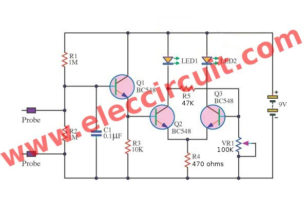
See in the circuit below. Operation of the circuit starts with R1 and R2 divide a supply voltage. And the probe checks the resistance of the skin that in parallel with R2.
So, the voltage drop across R2 depending on the resistance of the skin.
If the skin dries (people do not lie), the resistance of about 1M. The voltage is about 4.5V.
In another hand, if the skin moist (liar), the resistance is less than 1M. It makes the voltage is less than 4.5V.
This is a bias voltage for Q1 – BC548. Both Q1 and R3 is a buffer circuit.
Then, the voltage drop across R3 will be a bias Q2 to conducts.
And both Q2 and Q3 are a compare voltage circuit.
If the voltage at pin B of Q3 (voltage across VR1) is higher than the voltage at pin B of Q1 (voltage drop across R3).
Which is the voltage from the probe to measure the resistance of the skin. It makes LED2 lit to show the truth.
In contrast, if a lie, LED1 glows.
Parts will you need
Q1, Q2, Q3: BC548, 2N2222, 2SC1815, NPN Transistors
Resistors 0.25W, 5% metal/carbon film
R1, R2: 1M
R3: 10K
R4: 470 ohms
R5: 47K
LED1, LED2: LED(Light Emitting Diode) as you like
VR1: 100K Trimmer Potentiometer
Recommended: Learn Electronics with easy steps!
I builds this circuit with breadboard :
Note:
- The probe—you can use any copper plates or metal plates are slightly separated.
- The wire of R5 not connected to a collector lead of Q3.
- It is good enough for me. But maybe not good for you. We try building it to learn the working of transistors and basic. with a little game.
I love electronic circuit. I will collect a lot circuit electronic for teach my son and are useful for everyone.


I need Funclock Diagram For this lie detector circuit.
if these circuit will work or not
Hi, @hhh
It was my pleasure.
its a wrong circuit…. Q3 collector, led2 and R5 should not be connected and there will be an overlap…. my circuit led spoiled coz of the above lie detector…
Hi, all
Now, This circuit worked.
Please see in video.
Thanks,
Hi,All
Thank for your feedback.
This circuit works.
Please try again.
The wire of R5 not connected to a collector lead of Q3.
This circuit works,but the sensitivity is low.instade, I thing we can use comparator circuit(opamp)and increase the differential comparisin.
what u have used as a probe in this video…plez reply as soon as posssible!!!!!
which material have u used to connect it with probe!!!!…m not getting it by watching the video…plez tell me fast……..
i will surely help you.
my contact number is mentioned below
u can call me
number – 9011157145
This Circuit WORKS,,Please Check Your Wiring!!!!
Hi MR OHM 1970
Thanks for your feedback. I am happy because your friendship.