This is the Ham radio power supply circuit with RFI elimination for Amateur radio. The walkie-talkie requires RF Immune Power supply only. Why?
A typically Radio transmitters use High-frequency transistors as a current driver. So, it can cause very severe electromagnetic.
Sure, The power supply must be able to make the current higher than 10A.
How Ham radio power supply works
And most importantly, our power supply circuit must eliminate RFI (Radio Frequency Interence) as well. Let’s try to design a circuit better.
Pick it up(Designing)
A good power supply circuit for a walkie-talkie should have the following characteristics:
- Supply current at least 10A
- Keep constant voltage at 13.8V
- There is a function of Short Circuit Protection.
- Excess RF must be eliminated for antenna systems well.
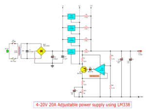
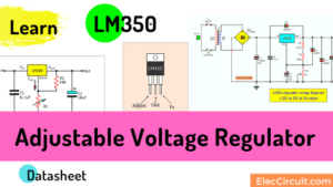
From design principles For the most economical We choose to use the instant IC, LM350T.
Read How to use LM350 and pinout
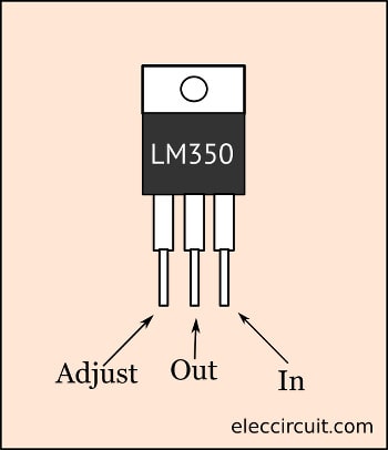
And it has a good cooling system with IC regulator regulations on the TO-220 chassis.
Read also: 7805 datasheet
The heatsink has a maximum temperature resistance of 1K / W. This IC is about 30 watts and has a voltage drop of up to 3 volts. This gives it a low drop voltage. It doesn’t work very hard.
Paralleling LM350 Regulator to increase current
See in the Block diagram below.
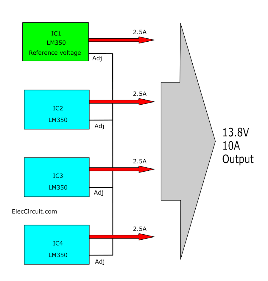
Normally, this IC can supply about 2.5A current, so we connect 4 of them in parallel, so the total current is 10A and or max 12A.
Set voltage IC to the same
But one of a problem in the many IC connections is the tolerance of the power supply system. Which is usually not too much.
However, a different voltage level may cause the output voltage to not be exactly as specified. Therefore, in parallel, it is necessary to have a voltage of 13.8V on all four units.
So we split this circuit into 2 sections. In order for the first IC to act as a reference IC. While the other 3 ICs have to adjust to that reference IC. By controlling VR1, VR2, and VR3 respectively.
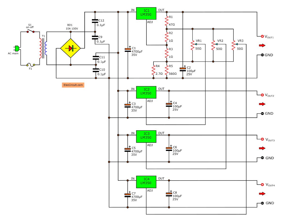
In this design, we designed the IC1 to be able to supply a voltage of 13.8V constant (theoretical).
This circuit defines voltage with the network resistors circuit consisting of R1 to R5 to adjust voltage as needed.
In its design it was found that instead of connecting the ADJ of the first IC directly to the resistor as usual.
We try to design it to maintain constant stability. There is R4 to reduce the total tolerance for this system.
If the value of R4 reduces, the output voltage also reduces. If the value of R4 increases, the output voltage also increases.
When IC1 has set the voltage level to 13.8V, we adjust VR1, VR2, VR3 so that the voltage is equal to the first IC (13.8V). And to compensate for mistakes We put the resistor R2, R3 to get a resistance equal to 2.2 ohms.
Meet Rs protection resistors
According to the output principle of each IC regulator. Should have a protective resistor Commonly known as Rs. But because Each output Must be connected to the real wire with a small resistance. Served as Rs.
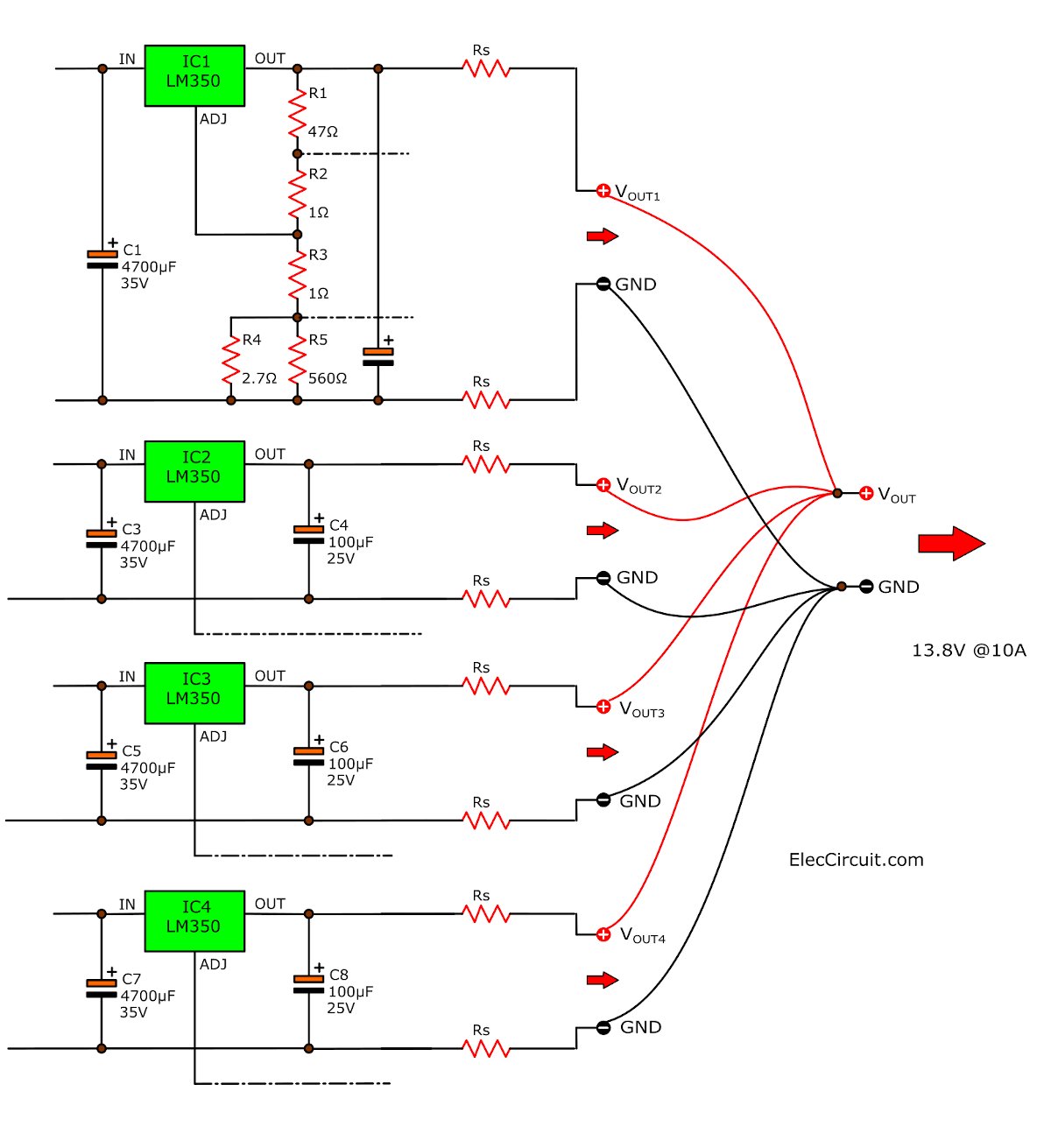
We use the power cable about 30 CM long, 0.7MM diameter. Go into the positive power outlet point and all 4 ground are connected together.
We assume that the resistance is now formed. On the output side of the regulator that is Rs equal to 30 milliohms.
If a short circuit occurs, it will stabilize itself well.
Asked if used with a high power booster How will it affect?
When a current of 3A is drawn, the voltage drop across the power cable is approximately 100mV. In practice, the output only changes 0.75% from the maximum voltage in the case of full load.
This is not a problem for radio transmitters.
You may also like these:
- LM338 Adjustable Power Supply 5A and 10A
- 5V 3A Switching Regulator using LM2576
- How change 7805 Voltage using Diodes
- < href="https://www.eleccircuit.com/simple-two-transistors-am-transmitter-circuit/" target="_blank" rel="noopener noreferrer">Simple Two Transistors AM Transmitter Circuit
- DC Boost Converter circuit 3-5V to 12V-13.8V
- FM wireless microphone circuit diagram
How to build
Although this circuit has a high current. But we can make it easy Because the essential equipment is IC and capacitor. It makes the circuit is smaller use transistors.
First prepare the components below.
Parts you will need
Resistors 0.5W
R1: 47 ohms
R2, R3: 1 ohms
R4: 10K
R5: 560 ohms
VR1, VR2, VR3: 50 ohms, POT potentiometer
Capacitors
C1,C3,C5,C7: 4700uF 35V: Electrolytic Capacitors
C2,C4,C6,C8: 100uF 25V: Electrolytic Capacitors
C9-C12: 0.1uF 50V, Polyester Capacitors
Semiconductors
BD1: 10A Bridge Diode
IC1-IC4: LM350T, 3A Adjustable Regulators
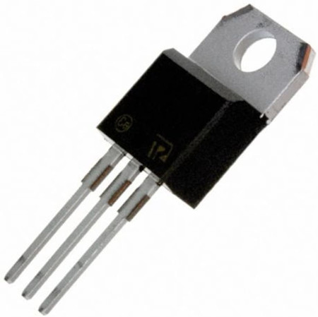
Thanks: Photo LM350T
T1: Toroidal transformer 18V 6A
Heatsink
and others
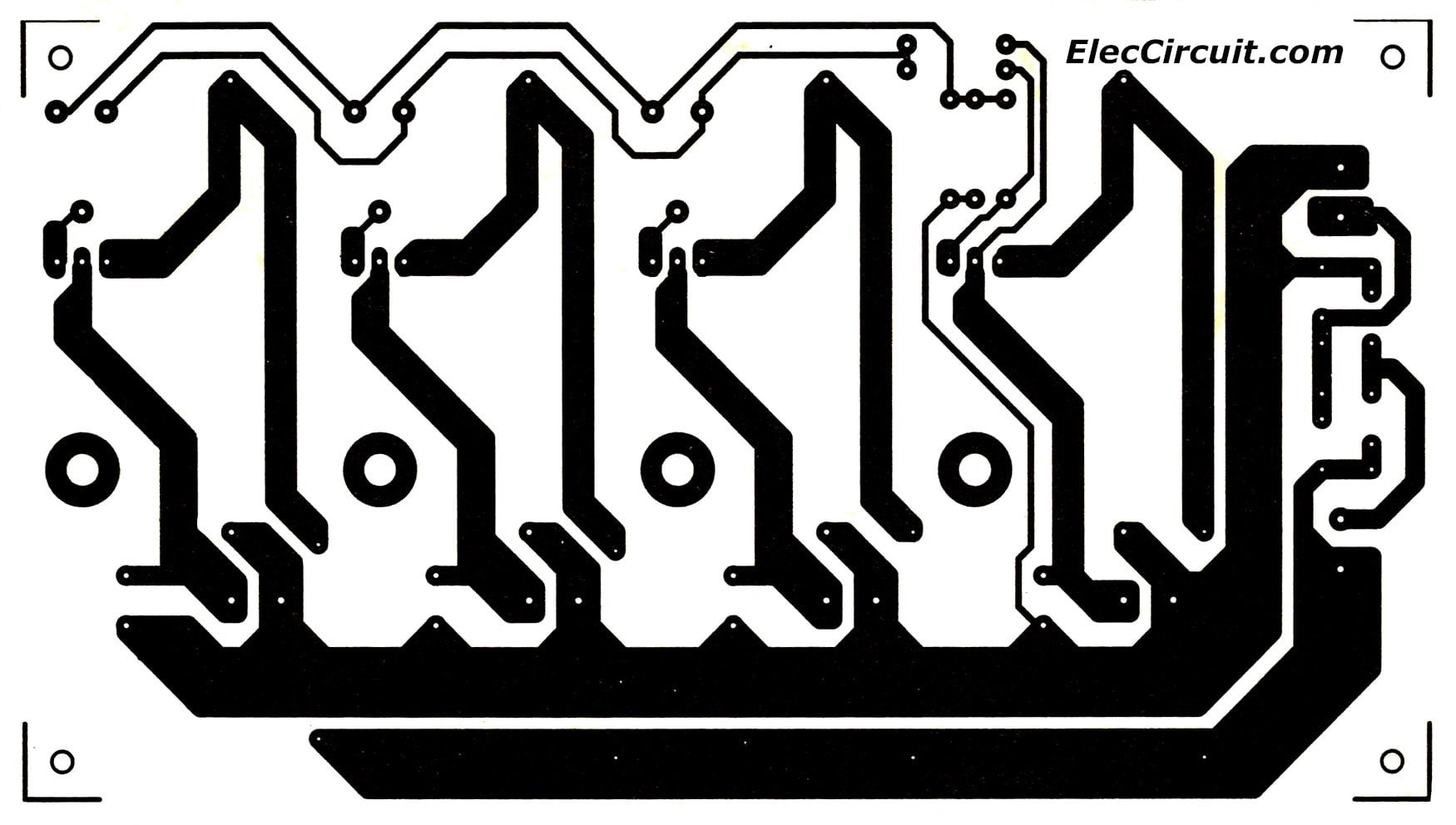
And build the PCB as the layout below.
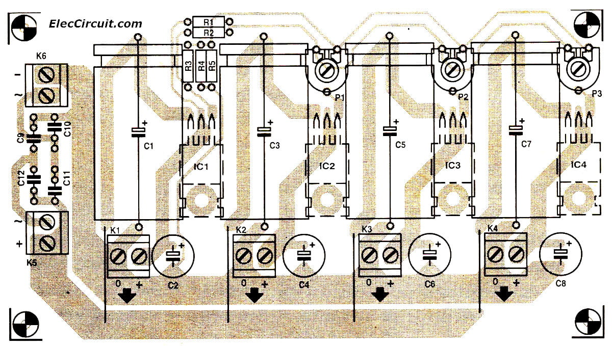
Then assemble the parts on PCB as component layout below.
Adjusting
We change R4 value for control the output voltage at 13.8V. Then adjust VR1, VR2, VR3 to control the output2, output3 and output4 at 13.8V all.
Then, parallel all output in one. Next, test dummy load at 5A. the voltage will be a stable output.
High Current 13.8V ham radio power supply (up to 30A)
GET UPDATE VIA EMAIL
I always try to make Electronics Learning Easy.
Related Posts

I love electronics. I have been learning about them through creating simple electronic circuits or small projects. And now I am also having my children do the same. Nevertheless, I hope you found the experiences we shared on this site useful and fulfilling.
Thanks.
Hi Salim Khan,
Thanks for your feedback.