I love Electronic circuits. I like to draw its line on paper. It’s not art. I think it’s science. But how does drawing not boring? Today I recommend that electronic symbols and diagrams may be answered. These symbols are very important in circuit design or drawing. They are a pictogram that shows instead of various real electronic devices.
Drawing real devices on paper is hard and slow. It is too boring. So far, I have drawn a lot of circuits on paper. It is fun. Back to learning knowledge…
Most of these electronic symbols are international standards of the IEEE standard (IEEE Std 315) and the British Standard (BS 3939). But may vary from country to country or engineering field, depending on the original convention. We will understand exactly the same. Also, we can make easily electronics projects and repair jobs.
The Circuit symbols list
Look at these symbols for different electronic devices below. You can click on each link to read more detail.
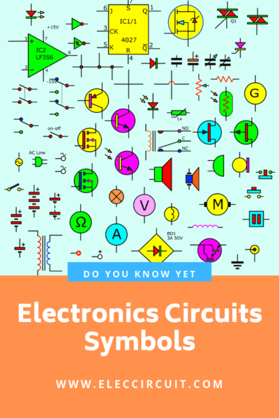
Since I want to design some symbols to be a difference of standard symbols. I love both the EU/IEC style and the US style.
So, I add color to make it interesting and different. My children like it. Do you like it?
Thus, some circuit symbols are not approved as a standard symbol. But I think most people can understand them.
Learn more: about Electronic circuits
Wire Symbols
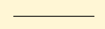
Wire Circuit Symbol
Description:
We use a wire to connect the electronic components to each other. All electrical and electronic components need wire to connect them to the circuit.
In a diagram called CIRCUIT DIAGRAM, the wires are drawn as lines.
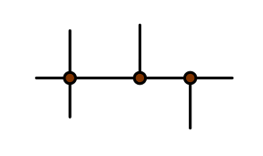
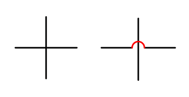
Wires Joined Circuit Symbol
Description:
When we connect the devices with other wires. They are joined together called Wires Joined Connection. it is best to place a dot on the connection to PROVE the lines are joined. They are shorted.
Remember when wires joined you must put a dot.
Unjoined Wires Components
Wires Not Joined Circuit Symbol
Description:
When the wires or lines may not touch or cross each other wires.
It is VERY IMPORTANT to show lines are NOT JOINED.
I use two Wires Not Joined Circuit Symbol.
For the beginner, I choose the second symbol it is clear to look like a bridge cross river.
Power supplies
Cell circuit Symbol
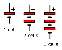
The cells are energy or power supply for a circuit.
Battery
Battery Circuit Symbol
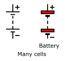
A battery (Abbreviated as ‘B’) is Supplies electrical energy. It consists of two or more cells. The positive terminal of the battery is always at the top and is the longest line on the battery symbol. You must add the voltage to the symbol. For example, 1.2V, 1.5V, 9V,12V. The symbol does not tell the voltage.
Recycle Free Li-ion battery from E-waste
DC Supply
DC Supply Circuit Symbol
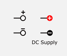
Often we use a DC power supply to the circuit instead of a battery. Also, the current will always flow in one direction. It has a positive and negative terminal. The positive supply is the Positive (+) voltage Connection. And, the negative supply is the negative (-) voltage Connection.
AC supply
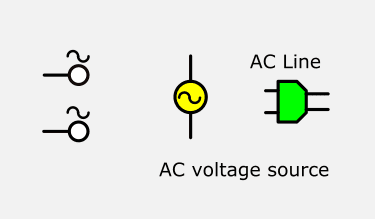
It is the main electrical energy in our house.
AC = Alternating Current Supply, continually changing direction.
Often I use a middle symbol is the AC voltage source. By the way, when using the AC line as the left symbol.
Switches
A switch can turn the power on and off. And sometimes we can use it to select different parts of a circuit.
SPST switch or ON-OFF switch
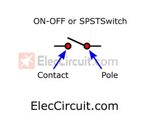
A simple on/off (single-pole, single-throw, or SPST) switch.
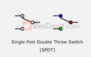
SPDT switch (Single Pole Double Throw Switch)
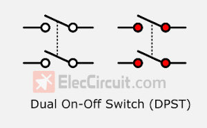
DPST switch (Dual Pole, Single throw Switch)
ON-OFF-ON SPDT switch
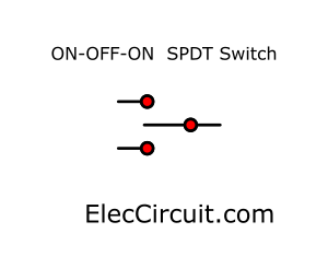
ON-Off-ON 3 Terminals, 3 Position SPDT Toggle Switch
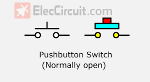
Push button switch (Normally open)
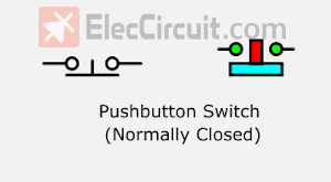
Normally Closed Push button Switch or Push-to-break switch
Fuse
Fuse Circuit Symbol
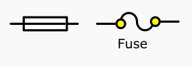
The Fuse(abbreviated with ‘F’)is a safety device. It will blow or melt. If the current flowing through it exceeds a specified value. To save the other devices from damage.
Transformer
Transformer Circuit Symbol
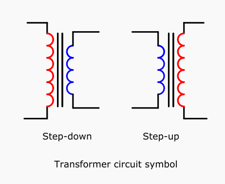
Description:
We often use a transformer(Abbreviated as ‘T’) as an AC voltage source. It includes two more windings, the primary and secondary. Which usually wrapped around an iron core.
There is no physical connection between the two coils. We can use transformers to step-up (increase) AC voltage. And, most used to step down (decrease) AC voltages.
A steady (DC) current will not be transferred from one coil to the other.
Earth Ground
Ground Circuit Symbol
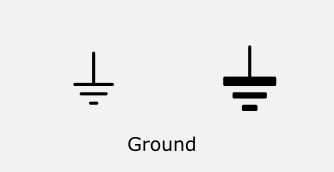
Description:
This is a connection to the earth. Normal is a negative connection. In many electronic circuits, this is the 0V (zero volts) of the power supply.
It is also known as ground(Abbreviated as ‘GND’). But for mains electricity and some radio circuits, it really means the earth.
Resistor Symbols
Resistor
Circuit Symbols: Resistor Circuit Symbol
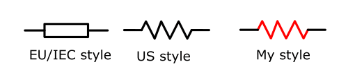
Description:
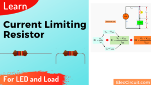
Resistors (abbreviated with ‘R’)resist the flow of electric current. We mostly use the resistors to divide a voltage into a smaller voltage.
For example, a resistor is in series with a LED to limit the current passing through the LED.
Variable Resistor (Potentiometer)
Circuit Symbols: Potentiometer Circuit Symbol
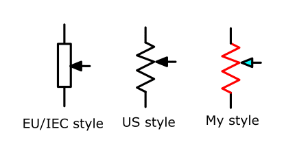
Description:
A potentiometer or pot trimmer (abbreviated with ‘POT’) is a type of variable resistor with 3 contacts. It is usually used to control voltage.
We can use it as a transducer converting position (angle of the control spindle) to an electrical signal.
Capacitor Symbols
Capacitor
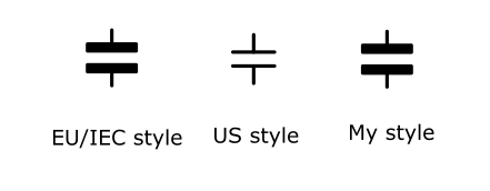
Circuit Symbols: Capacitor Circuit Symbol
Description:
A capacitor (Abbreviated with ‘C’.) stores electrical energy. It includes two conductors plates that are separated by an insulating. We called a dielectric.
A capacitor is used as a filter, with a resistor in a timing circuit. It can also to block DC signals but pass AC signals.
Learn more: Capacitor working principle
Polarized Capacitor
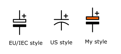
Capacitor-Polarised Circuit Symbols
Description:
A Polarized-capacitor stores electric charge, too. We must connect the correct way. If you reverse the connection may damage the capacitor.
The positive (+) or minus (-) lead of a polarized capacitor is always marked on the case. A capacitor is a filter.
It can also use it in a timer circuit by adding a resistor. Or block DC signals but pass AC signals as well.
Variable Capacitor
Variable Capacitor Circuit Symbol

Description:
We can change the capacitances of variable capacitors by rotating a rod the plates inside them. Normally, they have low capacity. Often we use this kind in a radio receiver turner and transmitters. The dielectric is Air.
Trimmer Capacitor
Trimmer Capacitor Circuit Symbol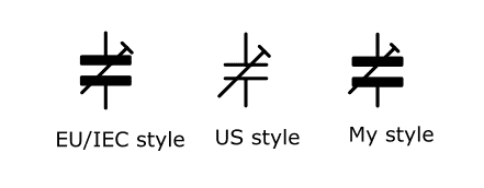
Description:
This is a type of variable capacitor. Most people called a trimmer. We adjust a capacitance with a small screwdriver or other tools.
Often see them it RF transmitter circuit and more. To set when the circuit works well. Then left without further adjustment.
Diode symbols
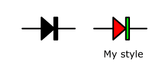
Rectifier Diode (Silicon Diode)
The electrical current will flow through the diode as one-way valves. Most we use them in the rectifier and protect backward current spike.
Light Emitting Diode (LED)
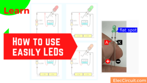
LED Circuit Symbol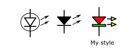
Description:
The LED is abbreviated as a light-emitting diode. It is a type of transducer that converts electrical energy or electric current to light. The LED is more efficient than many other light sources.
Zener Diode
Zener Diode circuit symbols
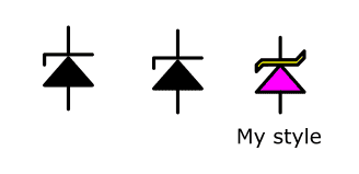
The Zener diode (abbreviated as ‘ZD’) is a special diode. It keeps a fixed voltage across its terminals. After a breakdown voltage, the device allows current to flow in the reverse direction.
LDR_Light Dependent Resistors
Another Variable Resistor is the light-dependent resistor (LDR). The LDR changes can conduct electric current with the changing of the light.
Read more: How to use Zener diodes, and example circuit
Transistor Symbols
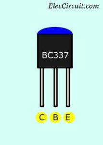
NPN Transistor
Transistor NPN Circuit Symbol
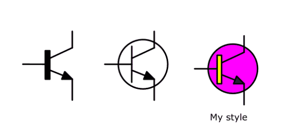
A transistor (Abbreviated as ‘Q’) amplifies current. It can run with other components to make an amplifier or switching circuit.
Small input current and a positive voltage come to its base. Then, it allows a large current to flow from collector to emitter.
The NPN transistor has a layer of P-type semiconductor fixed between two layers of N-type. Both are the emitter and collector.
PNP Transistor
Transistor PNP Circuit Symbol
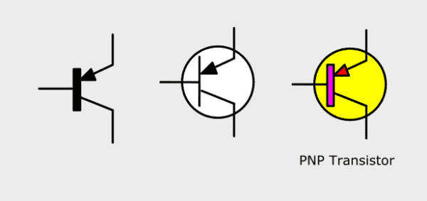
A PNP transistor (Abbreviated as ‘Q’) amplifies current. Not popular but importance! It works the same way as NPN types. But it runs in a negative voltage.
Small current comes to its base. Then, it allows a large current to flow from collector to emitter as well.
The PNP transistor has a layer of N-type semiconductor fixed between two layers of P-type.
Pinout of NPN transistors. For example:
A photodiode is a type of diode. We may call A light-sensitive diode. It works as a photo-detector and converts light into very weak voltage or current like Solar Cell.
Phototransistor
Phototransistor Circuit Symbol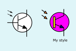
The phototransistor is a type of transistor. We called a light-sensitive transistor. Its working is similar to a normal bipolar transistor.
But it without a base lead. They convert light into a bias base current. Or the light controls the current flowing collector and emitter lead.
Thermistor
Thermistor Circuit Symbol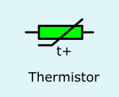
The thermistor (Abbreviated as ‘TH’) senses the heat content and converts it into resistance.
Audio and Radio Devices symbols
Speaker
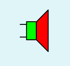
Speaker circuit symbol
Description:
The speaker is transducer devices. Which converts fluctuating current to sound. It can produce a much wider range of audio frequencies than a Piezo-Transducer device like the buzzer.
Piezo Transducer
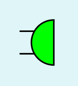
PiezoTransducer Circuit Symbol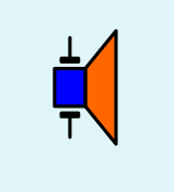
This transducer is a type of piezo speaker emit tone sound. It converts the electrical current into sound.
Buzzer
Buzzer circuit symbol
The buzzer produces a loud tone at a frequency of about 1500 Hertz.
Microphone
Microphone Circuit Symbol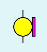
This device is a type of transducer. The microphone abbreviated as ‘MIC’. It converts sound to electrical energy.
XTAL Crystals
XTAL Crystals circuit symbol
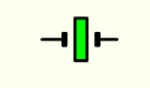
We use XTAL Crystals is an electronic oscillator circuit. This uses the mechanical resonance of a vibrating crystal of piezoelectric material. To make an output signal with a precise frequency.
Meter Symbols
voltmeter
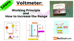
Voltmeter Circuit Symbol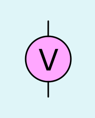
A voltmeter is used to measure the voltage at across two points in the circuit. The proper name for voltage is ‘potential difference’, but most people like to say voltage!
Ammeter
Ammeter Circuit Symbol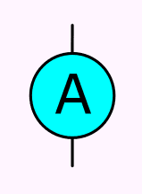
We use an ammeter to measure the current. It passes through the circuit at a particular point with series form.
Galvanometer
Galvanometer Circuit Symbol
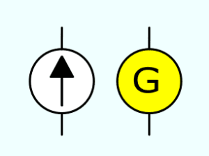
A galvanometer is a very sensitive meter which is used to measure tiny currents, usually 1mA or less.
Ohmmeter
Ohmmeter Circuit Symbol
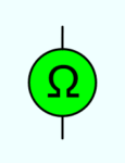
We use an ohmmeter to measure the resistance of many devices. Most multimeters have an ohmmeter setting.
Output Devices
Indicator Lamp
Lamp Indiator Circuit Symbol
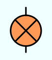
This is a transducer which converts electrical energy to light. It is a symbol of a lamp indicator. For example, a warning light on a car dashboard.
Globe or Lamp or Light bulbs
Globe circuit symbol
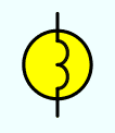
A globe has two connections (a fine wire inside a glass bulb glows when the globe is connected to a battery).
Motor
Motor Circuit Symbol
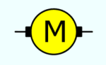
A motor(Abbreviated as ‘M’) is a transducer. Which converts electrical energy to mechanical energy (motion). Also, It can be a generator. To converts mechanical energy to electrical energy.
Inductor
Inductor Circuit Symbol
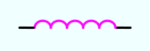
An inductor is a coil of wire. Which creates a magnetic field when current passes through it. It may have an iron core inside the coil.
Also, It is a transducer to convert electrical energy to mechanical energy by pulling on something.
Integrated Circuit
OP-Amp_Integrated Circuit
Nowadays my son designs all the circuit diagram and illustrates on our websites. He likes and enjoys this job very much. After he did it often. It made his work better and faster.
The Most Linear Circuit Symbols that his design in easyeda.com He says that he likes easyeda.com because It’s simple, flexible, fast.
Important updated version regularly and free too. The Figure below is also designed with easyeda.com for details on how to create each device. I suggest in my next article.
Note:
My article is not good enough. You can read other good websites.
Electronic symbol
Electronics circuit symbol
GET UPDATE VIA EMAIL
I always try to make Electronics Learning Easy.
Related Posts

I love electronics. I have been learning about them through creating simple electronic circuits or small projects. And now I am also having my children do the same. Nevertheless, I hope you found the experiences we shared on this site useful and fulfilling.
Nice post
Worth it, useful and thanks.
Hello Solomon Imariagbe,
Thanks for your feedback. Your text is my power.
Yes