When we are learning or building electronic circuits. And, sometimes you found unfamiliar electronic words. Now, we will learn two important words. They are impedance and reactance.
And, they have Definition, Formula, Types that interesting.
Although you can make an amplifier with good sound quality. Understanding these things is very useful as well.
Here is a step by step learning.
What is impedance
In the electronic, the impedance (The “Z” symbol) is the whole value against the current in the circuit. Or, it might be called the whole thing in the circuit that “impedes” the flow of current.
It is similar to resistance. But they are not the same. Because we have to take into account the effect of capacitance and inductance. The impedance is also measured in ohms, the symbol is the ohm (Ω).
| Resistance | Impedance |
| R = V/I | Z = V/I |
| Note: V = voltage in volts (V) I = current in amps (A) Z = impedance in ohms (Ω) R = resistance in ohms (Ω) |
The impedance is more complex than resistance. Because the frequency of the current flowing through in the circuit changes. It affects the impedance of capacitance and inductance.
Or it can be said that the impedance changes with frequency! But the change in frequency has no effect on resistance.
The term ‘Impedance’ is often used in simple circuits. Which do not have a capacitor or inductance (It is not wrong).
For example, when referring to ‘Input impedances’ or ‘Output impedance’ of a circuit. This can be confusing for those starting to learn electronics. But just imagine impedance is just another word for resistance.
There are four electrical quantities that determine the impedance (Z) of a circuit:
Resistance (R), capacitance (C), inductance (L), and frequency (f).
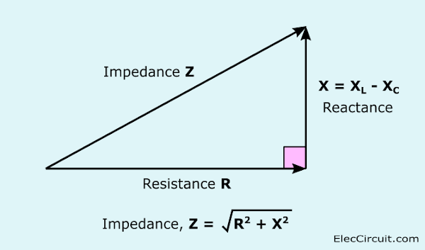
The impedance can be separated into two parts:
- Resistance R (It is the constant section regardless of frequency)
- Reactance X (It changes with frequency due to capacitance and inductance)
LEARN: Relationship Between Current and Voltage
Reactance details
The Capacitance and inductance cause a phase shift * between current and voltage.
We can combine resistance and reactance as impedance in a simple vector way. The reactance is perpendicular to resistance as shown in the figure.
What is Phase shift?
The Phase shift means Current and voltage do not move simultaneously.
Think about the capacitance of a capacitor.
- When the voltage across the capacitor is zero, the current is maximum.
- But when a capacitor is charged and has the maximum voltage, the current is the lowest.
Charging and discharging occur continuously alternately. The current will reach its maximum value before the voltage reaches its maximum value.
So we call that the voltage leading current.
Meet Reactance X
Reactance (symbol X) is a value that opposes the current of capacitance and inductance.
The reactance changes with the frequency of the electrical signal. And is measured in ohms, the symbol (Ω).
There are two types of reactance: capacitive reactance (Xc) and inductive reactance (XL).
Total reactance (X) is the difference between the two reactances: X = XL – Xc.
Thank you credit source: Impedance and reactances by John Hewes
Capacitance reactance Xc
- Xc = reactance in ohms (Ω)
- f = frequency in hertz (Hz)
- C = Capacitance in Farads (F)
Xc is large at low frequencies and small at high frequencies.
For constant DC where the frequency is zero, Xc is infinite. (Total resistance)
It is the origin of the rule that Capacitors allow AC to pass through. But blocking DC.
For example, a 1μF capacitor has a reactance of 3.2KΩ at a 50Hz signal.
But when the frequency is higher to 10kHz, its reactance is only 16Ω
If you still don’t understand clearly, READ: Electronics for beginners
Inductive reactance XL
- XL = reactance in ohms (Ω)
- f = frequency in Hertz (Hz)
- L = inductance in Henry (H)
XL is small at low frequencies and large at high frequencies.
For constant DC At zero frequency, XL is zero. (No resistance)
Is the origin of the rule that An inductor allows a DC to pass but blocks high frequency AC (AC).
For example, a 1mH inductor Only 0.3Ω reactance at 50Hz signal.
But when the frequency is higher to 10kHz, its reactance is 63Ω.
See other simple electronic circuits
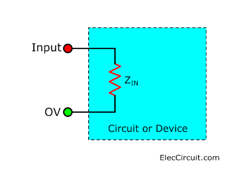
Input impedance ZIN
The input impedance (ZIN) is the impedance that looks into it. By what is connected to the inputs of the circuit or device (Such as an amplifier).
The input impedance is the total sum of the resistance, capacitance, and conductivity. Which is connected to the inputs on the inside of the circuit or device.
Usually we use the term ‘input impedance’. Although there is only an impedance in a circuit. And can use the word Instead, ‘input resistance’ can be substituted.
The truth is reasonable. If you understand that The input impedance is simply the resistance where the input signal has a low frequency (less than 1kHz).
How frequency affects capacitance and inductance?
This causes the input impedance to change with frequency. In general, the effect on capacitance and inductance is most important at high frequencies.
Normally the input impedance must be high. At least ten times the output impedance of the circuit. (Or device) that the input signal is input.
To ensure that the input is not overloaded with the signal source. This will cause the signal size reduced.
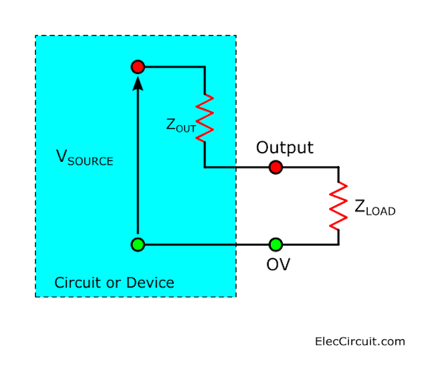
Output impedance ZOUT
The output of the circuit or device is comparable to the output impedance (ZOUT). It is connected in series with a voltage source (VSOURCE). Which we call the equivalent circuit.
And it represents the sum of the voltage generator, resistance, capacitance and inductance. That is connected to the output within a circuit or device.
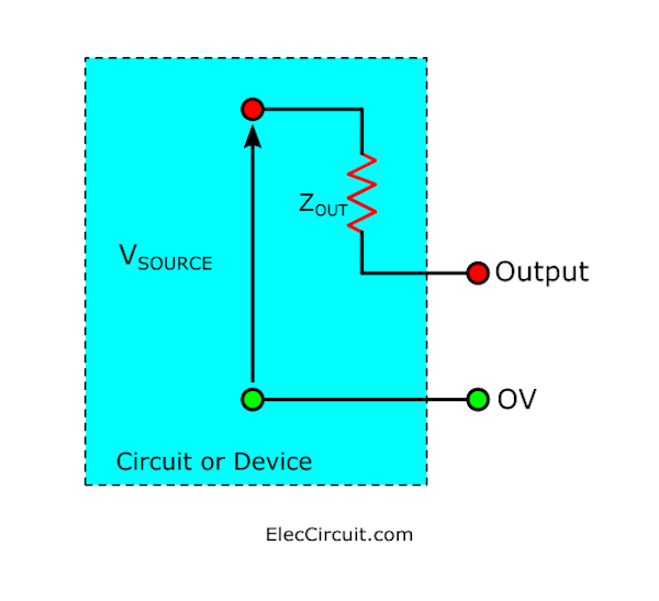
And we should know that VSOURCE is not a power supply(VS).
Usually we use the term ‘the output impedance’ as a general case, although only impedance is present in a circuit. And can use the word Instead, ‘output resistance’ is possible.
In fact, it makes sense to understand that The output impedance is simply the impedance that the output signal has a low frequency. (Below 1kHz).
As frequency affects capacitance and inductance, the output impedance changes with frequency.
In general, the effect on capacitance and inductance is the most important. At any high frequency.
Normally the output impedance must be low. It is ten times less than the impedance of load connected to the output.
If the output impedance is quite high. It will not be able to feed a signal that is strong enough to load.
Because the voltage of the signal is greatly lost, within the drive circuit through the output impedance ZOUT.
The load can be a single device. Or input impedance
Of other circuits
The characteristics of the output impedance and the load can occur in 3 cases:
- The output impedance is lower than ZOUT << ZLOAD.
Most VSOURCEs will appear across the load. There is very little loss of the driving voltage through the output impedance. This is usually the best method. - Matching impedance ZOUT = ZLOAD
Half of VSOURCE appears across the load. And the other half loses in driving current through the output impedance. This is useful in some situations. (Such as an amplifier driving speakers) Because it can deliver maximum power to the load. But keep in mind that half of the power is lost by driving the current through ZOUT. This makes it effective only 50%. - Output impedance is higher than ZOUT >> ZLOAD.
Only a small percentage of them appear across the load. Virtually all loss in driving current through the output impedance. This method is not satisfactory.
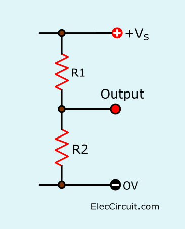
The output resistance of the voltage divider
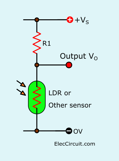
Voltage division, They are widely used in electronics, such as connecting a converter like an LDR to the input.
To be successful The output impedance of the voltage divider must be less than the input impedance of the connected circuit. Ideally, the output impedance must be ten times less than the input impedance.
Output impedance,
The VSOURCE voltage source in the equivalent circuit is the Vo output voltage when nothing is connected to the output (and therefore no output current) . This is called an ‘open circuit’ voltage.
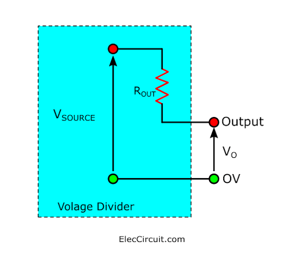
In a voltage divider, one resistor is the converter input, such as an LDR. Therefore, when the resistance of the converter changes, it will change both VSOURCE and ROUT too.
- Uses of capacitors | Capacitance | RC circuit time constant and Coupling
- Make High impedance preamplifier using a transistor
To check if the ROUT is low enough or not?
We have to try and find the maximum value that happens. When the converter has maximum resistance (It will affect the converter connected to the voltage divider.)
Example: If R1 = 10K and R2 is an LDR with maximum resistance 1M, ROUT = 10k × 1M / (10k + 1M) = 9.9kohm (approx 10kohm), that is, the load or input resistance must be at least 100kohm.
You may like to see these, too
- Low impedance input preamplifier | microphone speaker circuit
- Try simple FET Preamplifier circuit (Very high impedance)
- 4 types of Preamplifier circuits using Transistors

I love electronics. I have been learning about them through creating simple electronic circuits or small projects. And now I am also having my children do the same. Nevertheless, I hope you found the experiences we shared on this site useful and fulfilling.

There are a lot of IMPORTANT TOPICS Here…Please learn them!!!
You Made the explanation of Z , XL and XC Very Simple!!! Many Thanks!!!
Hi friend,
Thanks for your feedback.