If you would like to learn basic digital, but it is difficult and boring. Let’s try to create a LED chaser circuit or Running light circuit. It is used in computer games and in many scientific and mathematics applications so is best for a beginner or for kids to learn digital, also my son loves them.
Let’s get started IC 4017 project below!
The LED will glow one by one per period and it will cycle repeats as running light.
In-circuit uses IC-555 as an oscillator pulse generator and IC-4017 to drive LEDs.
Parts used in this circuit are easily available in most of the local markets.
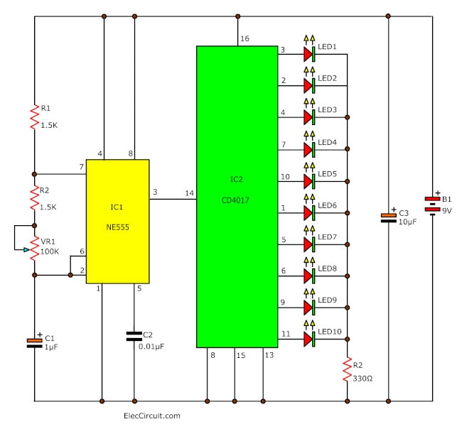
Chaser circuit using IC-4017 + IC-555
If you want to build a 10 LED Chaser circuit we recommend this circuit first.
The working principle
See in the circuit above. The IC555-IC1 is popular timer IC as the Astable Multivibrator or free-running pulse generator.
Which the output pulse frequency at pin 3 of IC1 is determined by R1, R2-1.5K, VR1-100K, and a capacitor C1-1uF.
The decade counter CD4017-IC2 act as a LED driver in 10 output, by LED will glow only one in a rapid sequence. Then, IC2 get pulses to the input pin 14.
Next, The 10 outputs Q0 to Q9 become active, one at a time, on the rising edge of the waveform from IC555, to drive the LEDs. The reset pin is 15 to the counting.
When one LED turns off, the second on turns on. This cycle LED repeats like loop the running light.
We can Adjust the speed of LED chaser or the pulse rate by rotating the 100K-VR1 trimer’s knob.
Parts you will need
IC: CD4017 Decade Counter Divider with 10 Decoded
IC: NE555, Timer IC = 1 pcs.
C1: 1uF 16V, Electrolytic capacitors
C2: 10uF 16V, Electrolytic capacitors
R1,R2: 1.5K, 0.25W Resistors 5%
VR: 100K, Trimer-potentiometer
LED1-LED10: LED as you want
B1: 9V battery Or 9V power supply circuit
etc.
Learn more: Great electronic supplies stores lists for you
My son experimented with this circuit on a breadboard.
This circuit is working in below
7 LED Light Sequencer circuit with adjusted speed
The LED light sequencer circuit, generally cannot adjust the speed of running. Cause dull monotony. Resulting in an idea to build this circuit up.
This circuit can adjust the speed of the led light as needed. Makes this circuit can be used more versatile.
Recommended: How does NE555 timer circuit works
Operation of the circuit has two sections:
First, Frequency generators and the display. Which the frequency generator IC1 contains a number Ic timer circuit 555 and frequency generator.
Defined by the R1, VR1, and C1 will be the output signal at pin 3 of IC1 sent to display section.
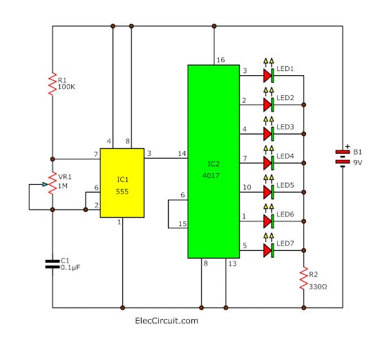
7 LED light sequencer circuits
Second, in the display section consists of IC2, a CD4017. It is Counter circuit display the volt at pin 3, 2, 4, 7, 10, 1 and 5, respectively each pin.
The speed depends on the frequency count obtained from pin 14 of IC2.
Which we can adjust VR1 to set the frequency from the frequency generator.
My son plays this circuit enjoy!
8 LED Light Sequencer Circuit
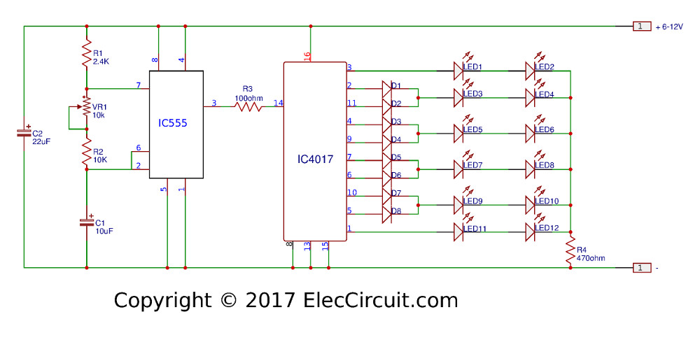
If you want an 8 LED Light Sequencer circuit. You can do it easily as circuit diagram below.
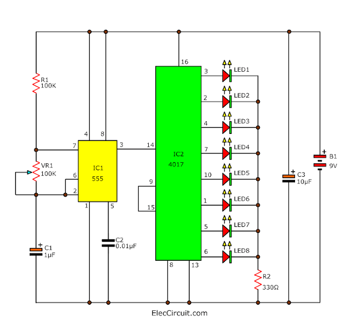
Add LED8 to pin 6. And, connect Pin 15 to Pin 9.
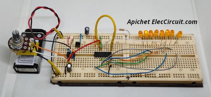
We test this circuit on a breadboard. It runs so well.
Next, let’s build a great project below with PCB…
Circle LED chaser circuit 4017 project
This is one of IC 4017 project that I like it. The Circle LED chaser circuit or 10 LED running light as another kind of string light circuit.
Which is running light on circle each one step beautifully and can adjust speed as well.
Read also: DIY Flashing Bicycle LED Taillight Circuit
The working principle
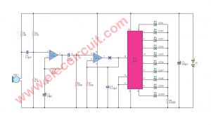
From circuit will see that we use two ICs. Which the IC1-NE555 as timer IC with a widely used general.
In this circuit will use the IC-555 as the square wave generator to output.
Which that frequency is determined by R-2.7K, R-470 ohms, and C-10uF 16V.
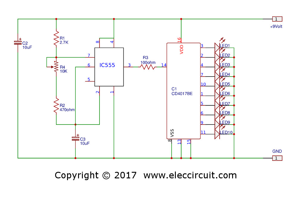
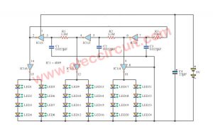
In addition, yet has a VR1-potentiometer-10K is frequency adjuster. When IC1-NE555 generate the frequency up, will be entered to IC2-CD4017 by through way of R 100 ohms. IC2 is Decade Counter IC will provide output is positive voltage Sort by Position according to an input signal from IC1-NE555 One end of the LED all. Which the pin K to pooling through R 1K to ground to as the throughway of current.
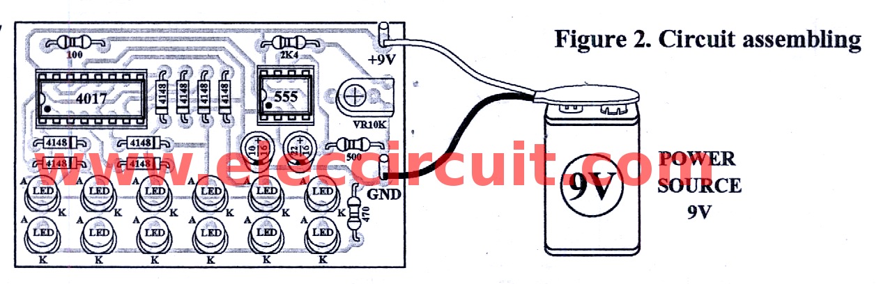
How to assemble circuits
You can build the PCB as the layout in Figure 2. Then Put all parts in PCB as components layout in Figure 3. Firstly, put small components type such as R, C, LED and socket IC into PCB. When solder finish, should check correctly.
Next, bring both IC to insert into the socket, careful do not Wrong terminal. When checking all thing correct then enter power supply into the circuit. Then, adjust trimmer potentiometer and noticed the running of LED if all that work normally so can use it now.
Keep reading: KEY CODE using 4017 project
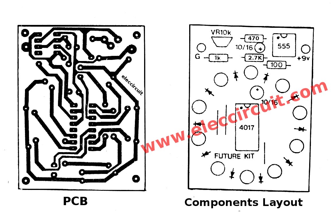
Figure 2 Single-sided PCB layout and Components layout of this projects
The circuit use power supply between 3-15V but to convenience should use 9V rectangular battery to best suitable. All resistors use size ¼ W. The LED will use all red or also use alternating red and green.
The components List.
IC-CD4017___Decade Counter Divider with 10 Decoded = 1 pcs.
IC-NE555_Timer IC = 1 pcs.
C-10uF 16V_Electrolytic capacitors_2 pcs.
0.25W 5% Resistor
R-2.7K = 1 pcs.
R-470 ohms = 1 pcs.
R_1K = 1 pcs.
VR_10K__trimer-potentiometer_1 pcs.
LED_as you need = 10 pcs.
etc.
LED Pattern Flasher circuit
The circuit uses a 555 timer oscillator to supply clock pulses of a variable frequency to the 4017 decade counter. The decade counter only needs to have three outputs so the fourth output goes into the reset pin to start the cycle all over again.
The central red led is always on. Each row of four LEDs flashes in sequence giving the impression that the light is rotating. It is an idea that works very well giving an eye-catching display. It will run continuously for three hours with a standard pp3 battery.
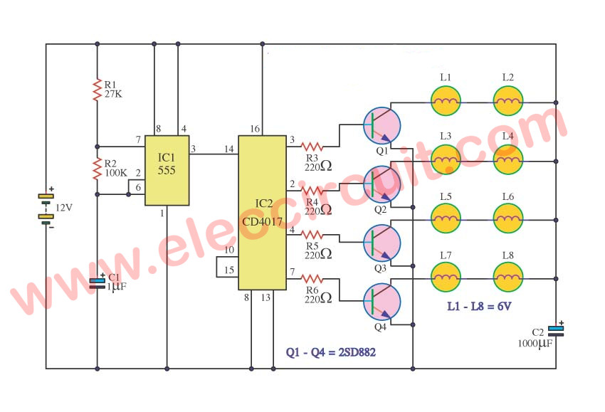
Two way 12 LED running lights using 4017
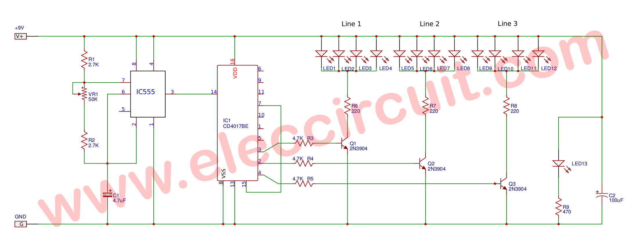
Here is the another of IC 4017 project This Two way LED running lights to use for beautiful. Which they are one of 4017 project that uses 12 LED lamps, arranged in 2 rows, each row of 6 LEDs. A green one and a red one, alternatively. use a different color for this.
Technical information
-The power supply of 6-12 VDC.
-Power consumption is about 12 mA maximum
-Have the speed of the flashing.
-PCB dimensions: 2.80 x 1.77 inches.
How it works
This circuit has 2 IC, IC1-555 is frequency generator, by this frequency can adjust at the 10K-potentiometer output of IC1 through R-100 ohms into pin 14 of IC-4017. The IC-4017 is Decade counter with 10 decoded outputs IC IC.
Which its output glowing will slide down each position, by begin from output at 1 is pin 3, 2, 4, 7, 10, 1, 5, 6, 9 and 11 in sequence.
When it to pin 11 the output light will back to pin 3 and continue to glow in sequence each step, by the signal from IC-555 in the circuit. Which we can set output at 6 positions then backward glow, by notice at the IC output pin as LED can reverse run. The 1N4148-Diodes to protects voltage from output to same LED point.
Guidelines to make 2 way LED chaser
The circuit assembling is shown in Figure 2 should begin low to high parts sequence, for Beautiful and simple. By beginning with diode, resistors and higher. And the parts have a different polarity such as Diode, Electrolytic Capacitors, and transistors etc.
Testing
To apply a power supply size 9-volts to the circuit will see LED glow continue to step to step run go and back. And can adjust speed up by adjusting at 10K-potentiometer.
Application
This circuit uses power from 9-12-volts Therefore can install in the car using voltage 12-volts.
The component list.
Resistors
R1: 2.4K
R2: 500 ohm
R3: 100 ohm
R4: 470 ohm
Trimmer Potentiometer
VR1: 10K or 103
Electrolytic Capacitor
C1: 22uF
C2: 10uF
IC1: NE555 Timer IC
IC2: CD4017
Diodes
D1-D8: 1N4148 75V 150mA Diodes
Siren light from running light
The siren light uses that general use motor help in the whirl lamp or refect go to around, which weigh very and when be usable go to for a long time will cause the wearing out. but if we modify light running pretend siren make get siren that weighs light and can be usable for a long time go up.
How it works
The work of the circuit will divide the work goes out to are 3 the part, be origin frequency part will compose IC1 555 numbers will perform frequency origin. Which fix get with the value of R1, R2 and C1. By send signal the frequency goes out pin 3 ways s of IC1 second part is the part of counter circuit. Which compose IC2 number CD4017. Which build the circuit counts 4 the order.
There is the order volt output at 3, 2, 4 pin and 7 respectively whirl to go to continually. Which the speed in the measurement is will under frequency signal at 14 pin of IC2 and in third part be lamp driver circuit.
Which compose Q1-Q4 and R3-R6 by have the principle works to are when have voltage level at pin 3 of IC2 have current flow through R3 reach pin B of Q1 make Q1 bias cause L1 and L2 stick bright in case same of at pin 2, 4 and 7. When have voltage level as a result make transistor work by Q1-Q4 will work respectively of a signal from pin 3, 2, 4 and 7 which make lamp bright in order.
If you want to see more Siren circuits please see them.
+ Most common emergency sirens circuits
+ Make Police siren circuits
+ High power siren circuit using CD40106
Modify a LED chaser circuit into the easy timer
The a LED chaser is popular, so we will modify it into the easy and cheap timer.
First,a appliance will works, while respective LEDs will flash, and until all LEDs go out. Then the appliance stop.
How it works.
In Figure 1 is the circuit. To begin with, to apply the cord and the appliance to outlet of the circuit. Secondly, briefly press the pushbutton switch-S1 and release slowly.
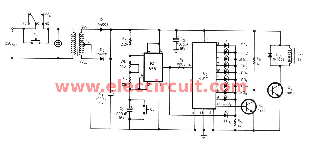
Figure 1 the circuit diagram of the easy timer
Suddenly, LED1 will shortly light up and LED2 will switched up instead, but LED1 will go out and will switch ON-OFF as the oscillation of IC1-555. And this will cause LED2-LED10 light up in sequence, until to the last LEDs then the circuit will also stop the appliance.
The VR1 use to adjust time in each step.
How to reset the circuit,first release it for 10 second, then press S1 and S2, the circuit will restart immediately.
10 LED roulette circuits using TC4011-LM4017 »
Related Posts


I love electronics. I have been learning about them through creating simple electronic circuits or small projects. And now I am also having my children do the same. Nevertheless, I hope you found the experiences we shared on this site useful and fulfilling.
#7 Led light running adjust speed
Sir i want clean figer and explainnation of all parts… And also i want to know how to run several led bulb by direct current… Plz tell me circuit
#7 Led light running adjust speed
Sir,I want to submit followed web site such as member of your company.
pls,I followed cause an electron.diploma in londontech international.
and working as anelectro.technician in saudiarabia.
thanking you.
sisil
#7 Led light running adjust speed
Pin 13 of the 4017 needs to go to ground although the picture shows it as pin 3 ( needs editing)
Thanks all,
Your comment are very important.
use it
component not easily available
Hi,gokul
This circuit worked but you check again.
Sir this one not operating.first led only glowing seqance not happened
#7 Led light running adjust speed
In answer to Alex Prasanth’s problem:
Thanks to the Admin for such a great LED project.
Alex, I’ve been able to run the circuit perfectly with 10 LEDs, but with a few minor modifications. 1. The decade counter (4017) would not move if you don’t have pins 13(enable) & 15(reset)grounded. So check that.
2. I removed R2(220 Ohms).
3. I am using C1 = 1uF
#7 Led light running adjust speed
Its nt working..!! All the LEDs are glowing..!!
Plz help..!!
Superb!!!
Thanks a lot
Its Working
nice wrking SIR
Can I have formula to calculate the pulse width/pulse frequency in this circuit??
It’s extremely urgent??
Kindly provide this..
#7 Led light running adjust speed
I’dont kow speed control please sir my email address
#Two way 12 LED running lights using CD4017 and NE555
what should be the working voltage for those 2 electrolytic capacitor.pls provide it
Use 25v
Hi,
@royal rodrix kumta
@arun
Thank for your feed back.
hi friend i tried this but only one led just glowing and it is not producing chasing effect..the 1st diagram(computerised one) and the working principle diagrams are diferent with the resistor valus please mail me how to do it please..thankq
i study electronic in my university. i interest to build the circuits. but i want to know the concept of the components.
Hi,
@Mukesh
@Pyae Phyoe Thwe Htoo
Thanks for your feedback.
good job buddy!!!!
Hello Sir,
i Am new in electronics. can u please help in making the led chaser with around 200 LED’s. Can you please send me the details of how to make 200 LED chaser with circuit diagram with its parts details.
Thanking You
Vaibhav Vats
can u please help in making the led chaser with around 200 LED’s. Can you please send me the details of how to make 200 LED chaser with circuit diagram with its parts details.
Thanking You
Bubai Das
Can u clarify my doubt sir? where to see the output of “Traffic light controller using 555 and 4017 IC’s (Multisim software used)” sir.
Hi! I have built the circle 10 led… it works fine but the slowest setting is still too fast than what i need.
Question: can i replace the 10k vr1 with 50k or 100k to make it go slower? If not, what should i do?
Thanks. 🙂
Hi,vaibhav vats
Thanks for your feedback.
Now, I not have circuits as you need.
I am sorry.
Hi,Fayaz
Thanks for your feedback.
Now,I not haveTraffic light controller.
I am sorry.
Hi,alex morfe
Thanks for your feedback.
You can use the variable resistor 100k,50k.
But it hard to adjustable frequency than 10k.
However you can reduce capacitor C-10uf to 1uf
hi chayapon,
thanks very much for the quick reply. i’ll try that 🙂
i have another question, but it is related to the dice circuit so i’ll just post it there.
thanks again.
Hi, alex morfe.
You are welcome.
can you please help me how to make a project with 10 led lights using an IC to control the lighting of the leds.. what best IC will be used in order for the led lights to have a pattern in their lighting?. Thank you very much. im hoping for your immediate response.
hi..
can you help me to make 100 LED’s Led chaser using decade. How to connect several IC,s in sequence. thanks
Then we’re is the 12th leg connect in ic 4017
Then where is the 12th leg connect in ic 4017
Dear Arun, 12th pin is “carry out” which is not required in this circuit.
hi sir i need to know how to lay out the ic pliz help i don’t know the forward or the backward in order to avoid reverse bias
Hi Arun,
Thanks for your feedback.
Not need to connects 12 pin. This circuit also works.
hai.can i know why the capacitors at the scematic circuit is not same from the list component at above.one the value is 10 and another is 1,but at list is both is 10.is that is same or not actually.
Hello , how about 50 leds ? Is it possible to series the led1 with 5 or more leds ? Pls reply , asap , I need your help , thanks
Hi Alec,
Thanks for feedback.
Now, I am sorry that cannot show you how to connect LEDs.
Please look at https://www.eleccircuit.com/siren-light-from-running-light/
or https://www.eleccircuit.com/siren-light-from-running-light/
#Simple 12 LED running using CD4017 and NE555
Pls send me to the pcb layout of simple 12 led running
may Allah add more knowledge to u add to us
Dear Sir please tell me the circuit diagram for making string light of 20 led light with blinking
What kind of diode to be use? #Two way 12 LED running lights using CD4017 and NE555
Hi saiet dey, I have an idea to make string light of 20 leds with blinking.(you will need extra 1- CD4017 IC, 2- PNP TRANSISTORS(such as A733), 2- NPN TRANSISTORS(such as 2SC828), 2- 1K RESISTORS and 1- 560ohm RESISTOR to upgrade this circuit .)
pcb
#Two way 12 LED running lights using CD4017 and NE555
can you put a clear copy of pcb layout
Thanks for the info mate
thank you for the useless information
Hi kedaran santhakumar,
Thanks for your feedback.
Great write up, very informative to new people like me.
If the input source was 12V, would this circuit still work reliably?
#7 Led light running adjust speed
Types of running LED light ,i am compete project work
Hello,
Whoever made the original post:
“As Figure 1 is LED chaser circuit whicn The CD4017 act as LED driver in 10 output, by LED will glow only one in a rapid sequence”
needs to work on their English.
thank you sir.
we are doing this as our first project
thqnk you for providing this information…….
Good stuff!
#7 Led light running adjust speed
Sir,can i join 10 extra LEDs parallel to the existing 10 LEDs?
Resp. Sir,
This sis my first project. I am new in electronics. can you please send me the parts list and circuit diagram so that I can make this “Circuit LED Chaser by IC 4017 + IC 555” circuit. and tell me the step by step working on this circuit
Thanks & Regards
Vaibhav
sir, pin no. 3 connected led only glowing when battery is connected.
before the use of switching what is the problem. .
pls reply. ……
can we use HCF4017 in place of CD4017?
Is we have to give input from frequency generator?
#7 Led light running adjust speed
Is it required to program by coding?
I dont have 10uf 16 v capacitor can i use 10uf 63v capacitor plz reply soon its urgent
Hi nitasha,
Thanks for your feedback.
Yes, you can use it replace IC-4017
Hi hardik bari,
Thanks for your question.
Yes you can use any frequency generator that not high voltage over 12V.
Hi kasim,
Thanks for your question.
Yes, you can use it. I hope you will enjoy this project.
This circuit didn’t work. It could only lit up only one LED. Afraid to see that internet is full of untested science projects and self-proclaimed ‘scientists’. The blogger didn’t even bothered to respond to this question, which was already asked by few more readers!! Dead Zone!
#7 Led light running adjust speed
Sir, can you comment or email to me the whole list of parts you use. Thank You 🙂
#7 Led light running adjust speed
@Kamran Siddiqi sir, can you please Email or comment the whole list of parts used? Thank you. This my email address. [email protected]
#Two way 12 LED running lights using CD4017 and NE555
I want to connect 100 led at outpin of ic 4017 using relay or scr connecting with output pin can it posible. Plz give suggestion I am waiting for your prompt responce.
@ANN:AH…Please use a 1N4148 switching Diode…Many Thanks From MROHM1970!!!!
Hi, thank you for the post. I did the circuit and it worked. I even added more leds and it is fine. However, can I remove the central led red light? If I do, do I need to remove the 100uf capacitor as well? Thank you.
#7 Led light running adjust speed
Discover how much your store can dual coupons to your particular
sum.
#Simple 12 LED running using CD4017 and NE555
Cool it works, but I have a problem, some of the LED’s are very dim. I had to use a 2.2uF Capacitor instead of 3.3 because I didnt have it available, could this be the problem?
i had try it the led’s are glowing but not in sequence.
plz guide us.led speen is not increasing and decreasing.
#7 Led light running adjust speed
One question, how can I change this circuit, ensuring that the LEDs remain lit when they light up.
Thank you
Sir,
I need to make to circuit similar to led blinking, but instead of blinking the led I need to blink 60w bulbs with 220 volt input .What should I do? Can you help me out.
Thank you for posting this LED Chaser. I made one of these years ago and powered it with a 9v battery. It was my first real project. Your web page brings back memories of that project. I mounted everything on a thin piece if wood. When the LEDs are in a straight line and chasing fairly quickly you can shake the lights back and forth. The resulting image is a sine wave. If you time the movement of the board just right the sine wave becomes stationary.
Can I connect 200 LEDs on this circuit by 5 channel.how the circuit works reserve forward.please tell me.
It is very good thank’s
Sir in diagram 100 ohm resistor is also there but in requirements list it is not mentioned
Kibdly clear the dought
how to i change that sequence in reverse order plz tell that method in same circuit.
very useful
How can I drive relay to create a 220V Bulb x 10 Chaser?
Hi,
About 7 LED Light Sequencer circuit in the article. How can I do 8 LED Sequencer ?
Thank you
Hello Hain Rodrik,
Thanks for your visit to my site.
I like the LED light Sequencer circuit. My daughter tests it on a breadboard. It runs so well.
Please read and see the circuit in the text again.
Have a good day.