I am going to show you, LED Decorative light circuit. Do you like a LED blink or running light? I like a circuit like this. Although you will do not build it now. But it also a good teacher, right?
If you have ever been to use a LED flasher. Some may wonder how the inverter gate working as an oscillator. How it works. Reads it you will more understand it.
And this circuit also is the next step of drive LED with just only CMOS digital, like CD4049 and other ic like this.
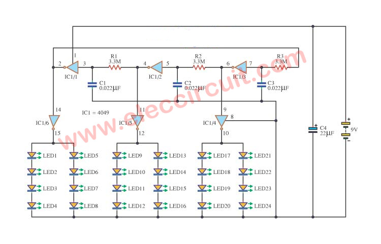
You may like this circuit the same me. It is amazing. Just only one IC can drive 24 LEDs to glow upon the 9V battery. It is so fun for a beginner like kids.
How it works
This circuit, the circuit will run at the IC not gate, the circuit arranged as a sequence. Work is in the initial condition at pin 3 of IC1 / 1 to 0 volts, will cause the voltage at pin 2 of IC1 / 1 to 9 volts.
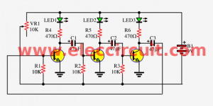
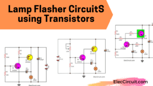
Also: 3 LED flasher using 3 transistors astable multivibrator
And: 1.5V 4 LEDs Flasher circuit using transistors
And pin 15 of IC1 / 6 to 0 volts, the LED1-LED8 not lit. However, due to pressure from the pin 2 of IC1 / 1 is connected to R3, C3 to charge through the R3.To Pin 7 of IC1 / 3 to 9 volts.
As a result, the voltage at Pin 6 to 0 volts, pin 10 of IC1 / 4 is 9 volts, the LED17-LED24 light.
Because pin 6 of IC1 / 3 R3 is connected to the pin 5. Of IC1 / 2 to 0 volts, as a result, the voltage at pin 4 to 9 volts. And pin 12 of IC1 / 5 is 0 volts, LED9-LED16 it off.
However, subsequent pressure on the leg 4 of IC1 / 1 to make pin 3 of IC1 / 1 to 9 volts. The next, LED1-LED8 light.
Read Also: Small Christmas LED flasher circuit with a sound
The order of the signal voltage at IC1 pin is pin 15, 12 and 10, respectively, were indefinite.
Read also: DIY Flashing Bicycle LED Taillight Circuit
Parts you will need
0.25W Resistors, tolerance: 5%
R1, R4, R3: 3.3M
Ceramic Capacitors
C1, C2, C3: 0.022µF 50V
Electrolytic Capacitors
C4: 22µF 25V
Semiconductors, Others
LED1-LED24: 5 mm Red LEDs
IC1: CD4049 CMOS Hex Inverting Buffer/Converter
B1: 9V battery Or 9V power supply circuit
Hand-picked related circuits you may want to read:
- LED Chaser circuit using 4017 and 555
- 20 LED Rear Bike Light Flasher circuit using 555
- 10 LED Roulette circuits
GET UPDATE VIA EMAIL
I always try to make Electronics Learning Easy.

I love electronics. I have been learning about them through creating simple electronic circuits or small projects. And now I am also having my children do the same. Nevertheless, I hope you found the experiences we shared on this site useful and fulfilling.
please mail me the details of this project