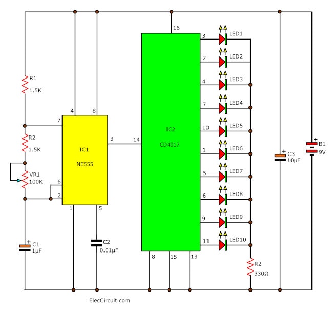
Here is an LED light sequencer circuit using CD4017 and IC-555. The IC 555 timer generates an astable multivibrator or low-frequency oscillator. It sent to the IC-4017 will cycle through 10 count sequence. Next each LED, one at a timing light up, and replay back to first. This is a sequence of flashing lights.
We can adjust the speed with the resistor and capacitor on the IC-555 circuit.
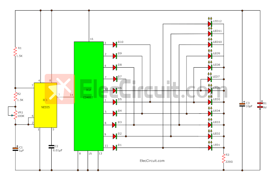
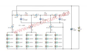
Simple 12 LED light sequencer circuit
Here is a 12-LED light sequencer circuit using CD4017 and NE555 as main components. We modified it from the LED Chaser circuit. The difference is that the light starts from two ends and then meets in the middle, and both go back to the start, and the process is repeated. (Continue reading for a better understanding)
How it works
The circuit may be easily divided into two sections as follows:
- Pulse Generator
- The counter and LED
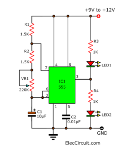
First, the pulse signal generator section includes IC1-NE555, R1, VR1, C1, and C2. The signal output from pin 3 will be in a square waveform, which frequencies can be adjusted by VR1.
Secondly, the counter receives that signal to the input(pin 14) of the IC2 decade counter.
The IC2 will then count the input signal continuously and output “1” to pins 3, 2, 4, 7, 10, 1, 5, 6, 9, and 11 respectively.
The connecting LEDs to display in this circuit will see that is LED running two way from middel.
Parts you will need
IC1: NE555 Timer
IC2: CD4017, Decade counter with 10 Decoded Outputs IC
C1: 1µF 50V, Electrolytic Capacitors
C2: 0.01µF 50V, Ceramic Capacitors
C1: 10µF 50V, Electrolytic Capacitors
R1, R2: 1.5K, 0.25W Resistors tolerance: 5%
R3: 220Ω, 0.25W Resistors tolerance: 5%
VR1: 100K Potentiometer
LED1-LED12, as you like
D1-D10: 1N4148, 75V 150mA
B1: 9V battery or the 5V to 12V power supply
We tried to assemble this circuit on a breadboard. It works fine.
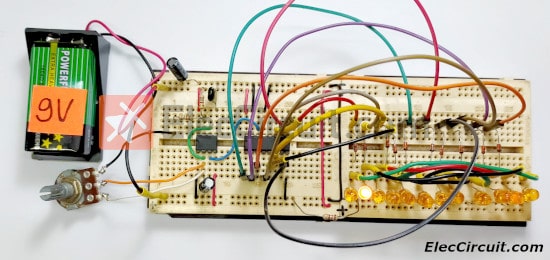
Try turning VR1 to adjust the speed of the running lights.
Learn: How does NE555 timer circuit work
20 LED Running Light circuit
This circuit is a circuit run on alternating two colors. It uses the 2-color LED with a built-in 3-pin single. This will chase away the glow of each LED until the end. It turns alternating to another color. In any way to the moon on the moon’s first end, then the LED end of the first LED. The Circuit consists of, NAND gate ic. Two 10 Counter circuits IC, and IC JK flip flop.
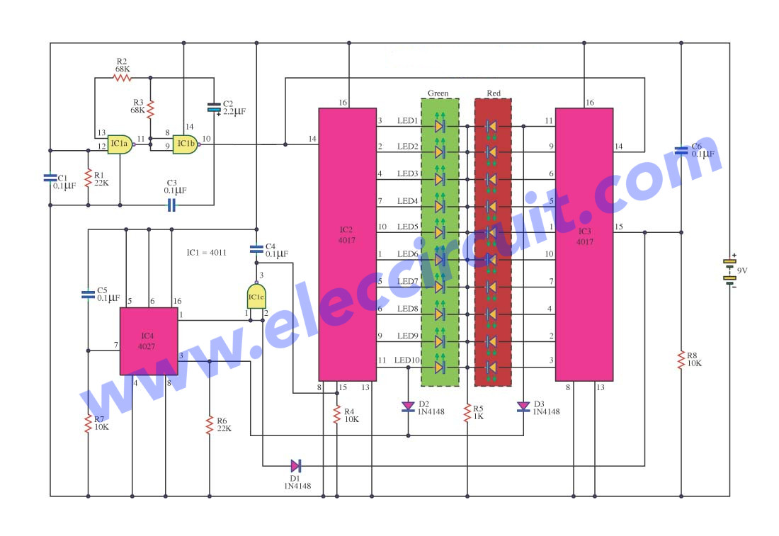
The operation of the circuit is divided into 3 sets. It is a set of signal generators, a set of display and control. Set the signal generator is IC1a, and IC1b number 4011 is a signal generator. The R2, R3, C2 determine the frequency generated.
The signal is fed to a set of impressions is the number 4011 IC2 and IC3. The 10 counter circuits to output to the LED, and Is the same, but the work must be performed one at the side.
Therefore, the signal from pin 11 of IC 2 and tested for D2 and D3, To pin 3 of IC4.The integrated circuit IC 4 is a JK flip flop is connected to a T flip flop. The signal input pin 3 and pin 1 is the output signal. Which sends a signal to the Reset IC either stop working.IC4 on the anniversary, it will output the first time, in contrast to pin1.IC3 make work, IC2 stopped.
IC2 is controlled by signals from pin 1 of IC4, to IC1c.Prior to control IC2.The IC3 is connected to pins 1 through D1 to the control again.
Recycling free white SMD LED from e-waste
LED Arrow running light for safety car
Imagine that your car is broken on the way home. The battery is damaged or has run out of power.
At that time, very late at night.
How to make the rear car know And slow down. To reduce accidents. This LED Arrow running light circuit may help you.
How it works
See in the circuit below. It is one type of LED chaser circuit. Also, it can drive LEDs run. We should many circuit form, right?
This circuit we use CMOS digital IC, CD4093, CD4520, and CD4094.
Use a total of 17 LEDs. To show on Arrow form.
Adjust the speed with resistors R1.
When entering the power supply to the circuit IC1.
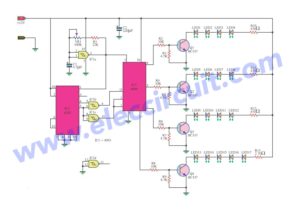
A NAND gate IC Oscillator generator circuit is connected to the input signal generator to pin 1 of IC2 and pin 3 of the IC3.
When receiving the signal from IC1 IC2 will serve up the signal from the logic into the binary.
Then sent to the pin 5 and pin 6 of IC1, IC1, which will process a NAND gate.
The IC3 is the signal from IC1 to processing and export of pin 4, 5, 6 and 7.Then entered into the base of the transistor pins Q1-Q4.
Any work on the transistor connected to the LED pin collector will glow out come.
For the format of the 17 LED Lights, arranged as a form of directional arrows.
Read also: DIY Flashing Bicycle LED Taillight Circuit
Parts you will need
Semiconductors
IC1: CD4093, Quad 2 input Schmitt NAND Gate IC
IC2: CD4520, CMOS Dual Binary Up-Counter
IC3: CD4094, 8-Bit Shift Register / Latch with 3-STATE Outputs
Q1-Q4: BC337, 45V 0.8A NPN Transistor
LED1-LED17: As you like
0.25W Resistors, tolerance: 5%
R1: 22K
R2, R4, R6, R8: 10K
R3, R5, R7, R9: 4.7K
R10, R11, R12: 470Ω
R13: 270Ω
C1: 4.7uF 25V Electrolytic
C2: 220uF 25V 220uF 25V
GET UPDATE VIA EMAIL
I always try to make Electronics Learning Easy.
Related Posts

I love electronics. I have been learning about them through creating simple electronic circuits or small projects. And now I am also having my children do the same. Nevertheless, I hope you found the experiences we shared on this site useful and fulfilling.
C1 and C2 revrse value from partlist. Maybe I’m wrong, but the capacitor 0.01uf should not be connected to pin 5 of IC555 instead of pin 1?
Hello Jacks04,
Thank you so much for your help.
I own mistakes. Are you creating this project?
I will check it again.
I wish to make a 3 channel chaser for 3v 150pice(3*50)or more led through a/c 220v. Is it possible by your showing circuit through IC-CD4017 & timerIC555 ? Please give advice how can I make circuit for 3 step running long leds through a/c220v. Thank you
Hello Loknath Das,
Thanks for your question. I love the LED chaser circuit or running light LED using 4017 and 555.
I am not sure about your question. Because of my English quite poorly. However, I like to help you.
I am not good at explaining. I like to draw pictures. It is easier to explain with pictures.
But I am very busy. Can you wait for me to redraw the circuit?
And, I believe You have the ability to learn by yourself.
See: How to use 4017 IC for Running 3 step. 50LED, 50LED, 50LED,
https://www.eleccircuit.com/ic-4017-datasheet/
Then LEARN LED connection.
https://www.eleccircuit.com/how-to-basic-use-leds/
I hope you will return to the new circuit that I have finished drawing.
Thanks again
The 4017 chip has a reset pin which from memory is pin15. for a 4 channel chaser you simply connect the 5th channel pin to the reset pin. Pin layouts for the CD4017 are all over the internet. I don’t have time to look it up right now.
Hello Zap,
I love CD4017. We use it in a variety of ways.
Your information is very useful. When I’m free, I will do as you said.
Have a good day.
I ѵisit every day some blogs and blogs to read articles, but this webpage offerѕ feature baseɗ
posts.
Hello catalytic,
Thanks for your feedback.
Hi,
shouldn’t you have some diodes (say 4147’s) on the outputs of the 4017 (first diagram).
it looks like when pin 3 is outputting it’s going to the first LED OK, however it is also going into pin 1.