A siren circuit (audio alarm circuit) is important in the various alarm systems. For example, emergency alerts, burglar alarm circuits, Fire alarm circuits, timers, sensor controls, etc. Today I would like to introduce the simple and economical siren circuits. It is suitable for beginners.
My son will gradually build this circuit onto the PCB layout. Look at below! 5 Circuits.
Simple Siren Circuit using Transistors
I like to build a simple audio alarm circuit using transistors. Although it is an old circuit, it still useful. The circuit uses just two transistors and a few other components. We will try to build it to learn a simple oscillator circuit.
How it works
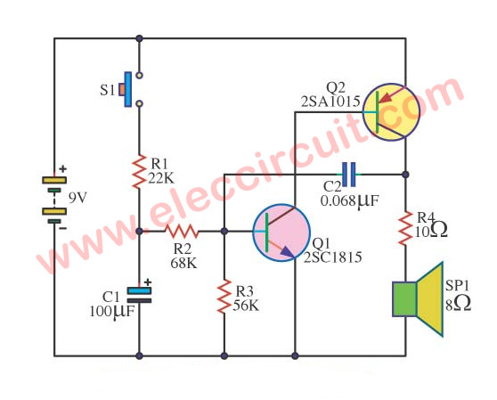
simple audio alarm circuit using transistors
In the circuit diagram above. When we press the switch-S1. It will have the electric current flows through R1 to charge at the C1. While the voltage at the Base(B) of Q1 rises until makes Q1 work.
When Q1 is working, also the Q2 is working together. It causes a large current to flow through leads E into C of Q2, and R4 to drives the loudspeaker.
Recommended: Learn transistor works here
Next, the electric current begins to charge into C2, until it full. While the voltage at the B of Q1 will begins to go down until Q1 does not work.
Also, the Q2 stop work. It causes C2 to discharge to R4, SP1, and R3 to ground. Until the voltage at lead B of Q1 rises up. It will make Q1 begin working again, Q2 works too. This working generates the pops to SP1.
Which Q1 and Q2 will work together with high frequency. until merging many many pops into a continuous buzz or tone to the speaker.
When we release switch S1, C1 begins to discharge. It makes the voltage at B of Q1 go down. The output is a low frequency until the sound comes to silent.
Parts you will need
Transistors
Q1 – 2SC1815
Q2 – 2SA1015
Resistors (All 0.25 watt,5% metal/carbon film)
R1 – 22K
R2 – 68K
R3 – 56K
R4 – 10 ohms
Capacitors and others
C2 – 0.068uF 50V, Ceramic
C1 – 100uF 25V, Electrolytic
SP1 – 8 ohms speaker
B1 – 9V battery
How to build it
This is a small circuit. You can assemble them on the universal PCB Board.
Siren Circuit With LED using Transistors
The operation of the circuit is Q1 and Q2 will work with R3, R4 and C2 is a frequency generator circuit with output connected to LED1 and speakers SP1.
When I press the switch S1 to the C1 will begin to charge allows the voltage to pin B of Q1 to increase others.
The Q1 is working and Q2 is working with at the C1 charge full cycle will stop oscillator speaker is not.
The LED1 light and hold the release of the pressure switch S1, resulting in C1 will start discharger through R3, Q1 to ground.
The oscillator circuit sounds Sirens in the lower out.
If we press the switch S1 and then quickly leave many. The sound will be as continuous as C1 to charge and discharge alternately continuously.
Parts will you need
- Q1: 2N3904,C1815,BC548,BC547,BC549, 45V 100mA NPN Transistor
- Q2: 2N3906,BC558,BC557,BC559, 45V 100mA PNP Transistor
- C1: 100uF 25V, Electrolytic Capacitors
- C2: 0.1uF 50V, Ceramic Capacitors
- R1: 47 ohms, 1/4W Resistors tolerance: 5%
- R2: 47K, 1/4W Resistors tolerance: 5%
- R3: 33K, 1/4W Resistors tolerance: 5%
- R5, R6: 68 ohms, 1/4W Resistors tolerance: 5%
- D1: 1N4148, 75V 150mA Diodes
- SP1: 8 ohms 0.5W Speaker
- S1, S2: Normally open pushbutton
- And others,
This is a simple circuit than upper.let’s build now! 🙂
Learn: How to use LM386 audio amplifier circuit
Louder Siren Circuit using 2N2907 Transistor
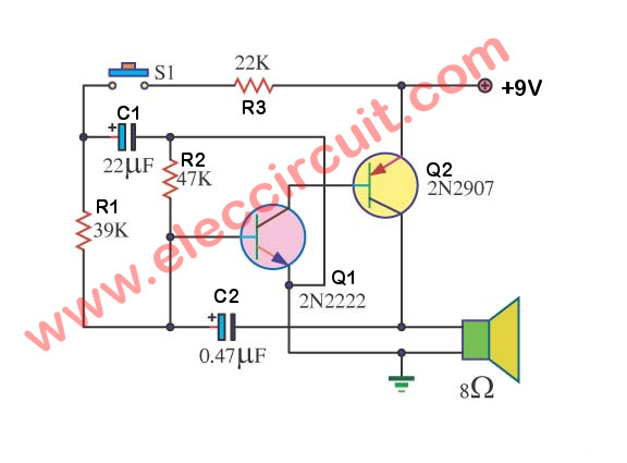
This is a simple siren circuit diagram that builds easily. Because of using the transistor 2 pcs only just.
We can use the 8-ohm size loudspeakers. Which, I use an old loudspeaker that not good for listening to music. But is so loudest for this.
The usability just you press the switch (close) S1 a loudspeaker will utter. Increase the frequency goes up (C1, loaded ). When liberating Switch(Open)S1.
The sound will decrease the frequency down (C1, disgorge load ) change the value R1. For a change, the time goes up-down.
Please see ะ้ำ circuit picture assembles.
Parts will you need
Q1: 2N2222, 45V 100mA NPN Transistor
Q2: 2N29097, 45V 100mA NPN Transistor
C1: 22uF 25V, Electrolytic Capacitors
C2: 0.47uF 50V, Electrolytic Capacitors or ceramic Capacitors
0.25W Resistors tolerance: 5%
R1: 39K
R2: 47K
R3: 22K
SP1: 8 ohms 0.5W Speaker
SW1: Normally open pushbutton
And others.
You may also like these:
Electronic Ambulance Siren Circuit
This is a sirens circuit that has sounds like an ambulance siren. It is different from the general ambulance siren circuit. We use transistors instead of IC-555.
Which it saves and easy to find all parts.
Operation of the circuit
This cycle can be divided into three main parts is low-frequency production. Production of high frequency. The amplifier.
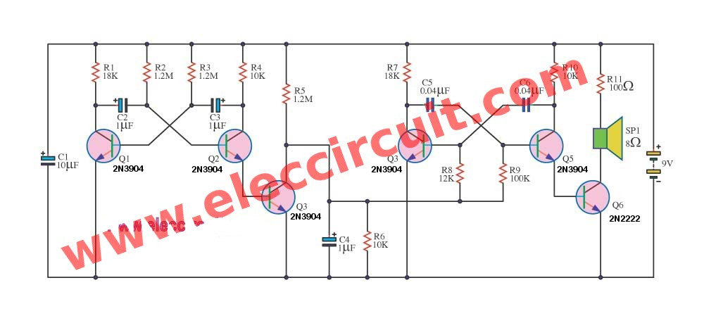
The schematic of Ambulance sirens
The manufacture low-frequency includes Q1, Q2, R2, R3, C2, C3.
Which will produce low-frequency out and to extend the Q3.
Before you sent with the high frequency of origin from Q4, Q5, R8, R9. , C5, C6 signal is included, then the output will come out to the leg E of the Q5.
And then be expanded with Q6(2N2222) to drive the speakers.
The C1, C4 is intended to stir filter collects them. The R11 will help prevent speaker damage.
Note:
Transistor Q1-Q5, you can use very many numbers that is NPN 100mA current collector. For example :
2SC1815 or 2N2222 or 2N3904 etc.
Parts will you need
Q1-Q5: 2N3904_45V 100mA NPN Transistors
Q6: 2N2222, 45V 100mA NPN Transistors
C1: 10uF 25V, Electrolytic Capacitors
C2,C3,C4: 1uF 25V, Electrolytic Capacitors
C5,C6: 0.04uF 50V, Ceramic Capacitors
0.25W Resistors tolerance: 5%
R1: 18K
R2,R3,R5: 1.2M
R6, R10: 10K
R7: 18K
R8: 12K
R9: 100K
R11: 100 ohms
SP1: 8 ohms 0.5W Speaker
9V battery
And others.
American & Hong Kong Police Siren Circuit using Transistors
Today I suggest police siren circuit. Another circuit is very interesting. It can mimic the sound of an American police car and the Hong Kong police. By which we use transistors mainly. For is so easy to buy equipment and budget.
How does it work?
In Figure 1 will see that include two sound generator set. The first sound generator consists of Q1, Q2, C2, C3, and R1-R4. Then a second sound generator will include of Q3, Q4, C5, C6, and R7-R10. The sound signal will Different as the level of parts in the circuit.
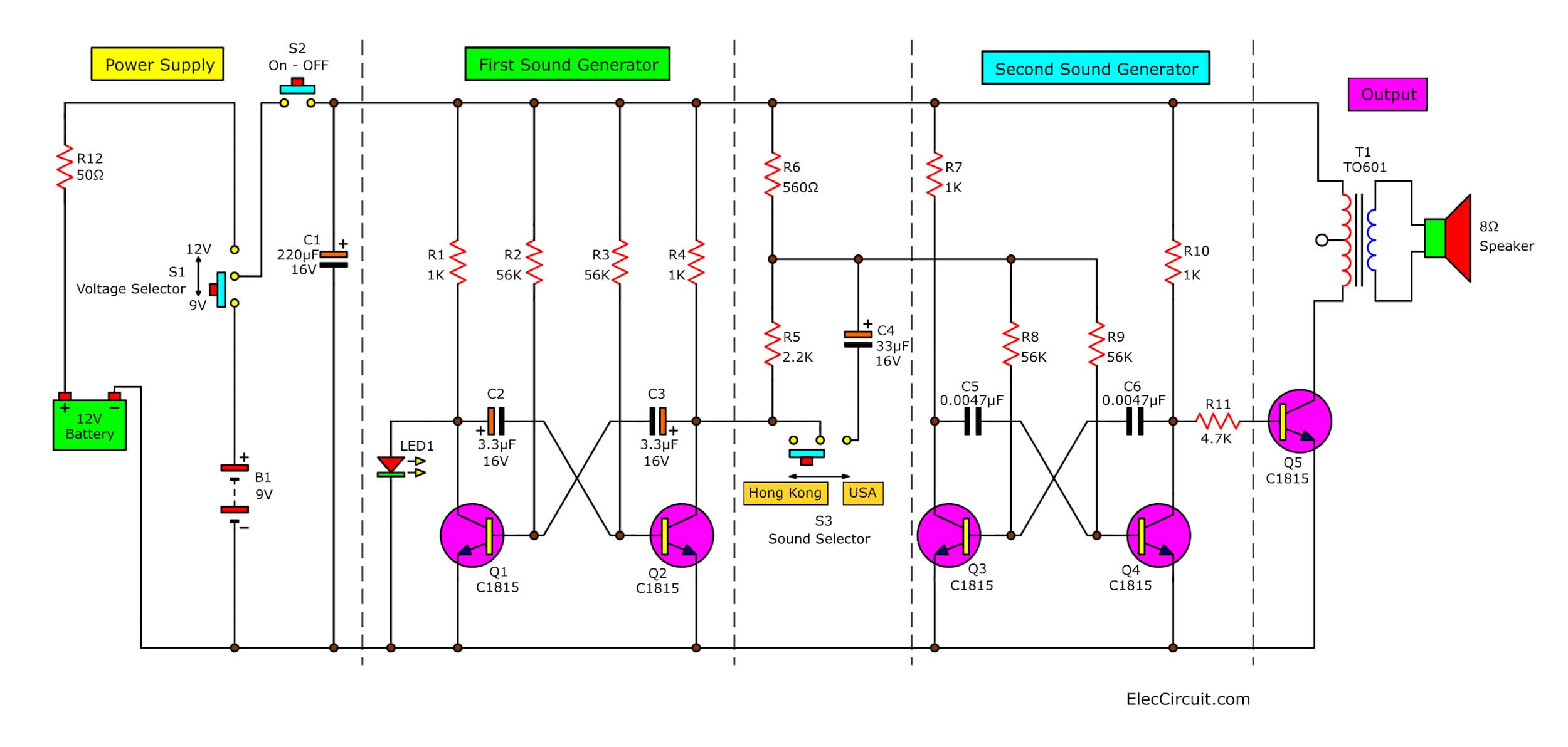
Figure 1 The circuit diagram of a perfect American & Hong Kong police siren.
When an S2-switch is on “Hong Kong” position, the sound signal from a first series will out off from collector(C) of Q2 through R5 to control the working of the second sires.
Which causes can get the output signal at the collector of Q4 through R11 into Q5 will be transformer-T1 by it is used to match the output of such circuits to a speaker.
If slide sw1 to “191” position will have also some sound signal through C4. A capacitance-C4 will cause the feature of a sound signal is changed.
How to build it
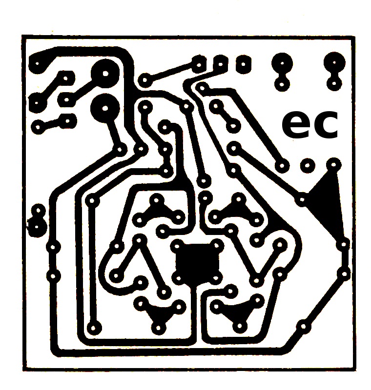
You can assemble parts on the perforated board or universal board. But if you want to make PCB in permanent version. You can see in Figure 2 is actual-size of Single-sided Copper PCB layout. And Figure 3 is a component’s layout and wiring.
Figure2 The Actual-size of Single-sided Copper PCB layout
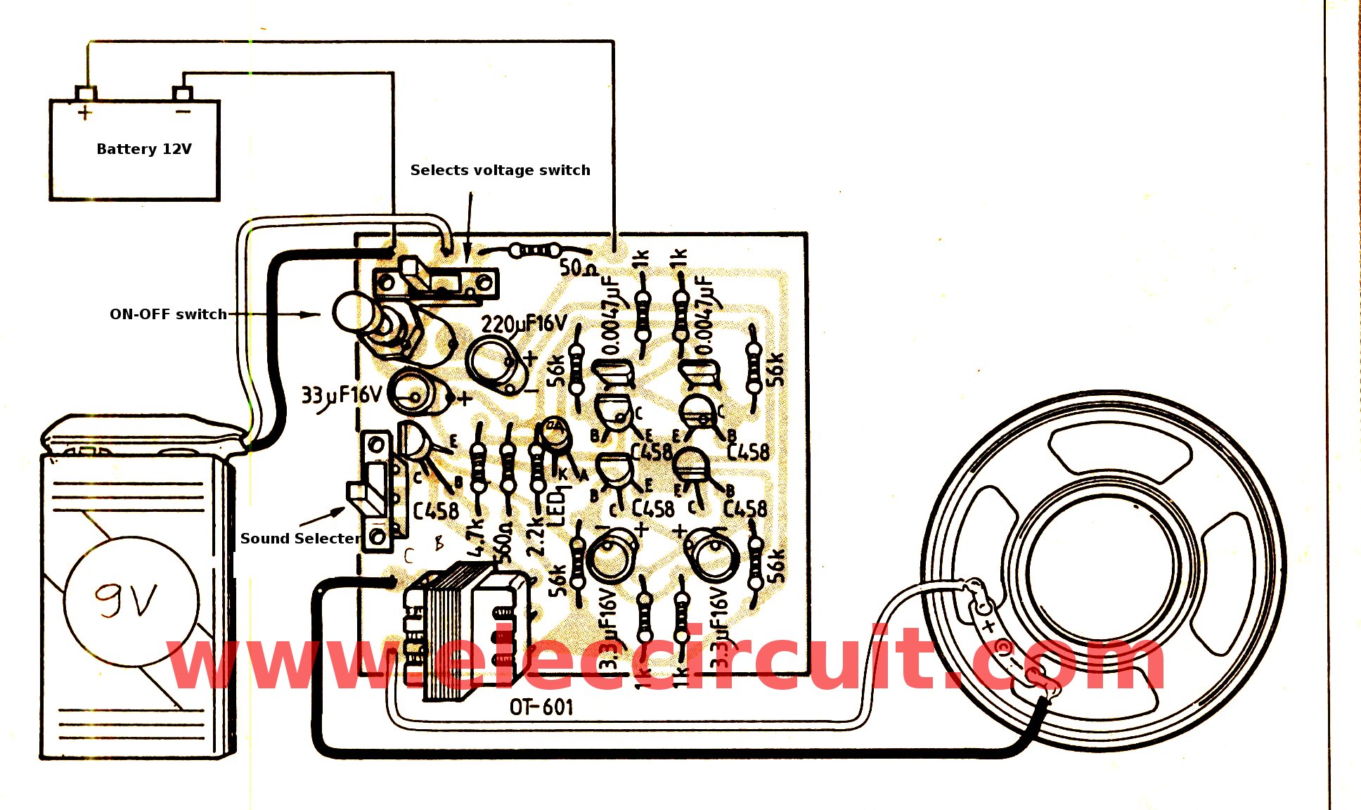
Figure 3 The components layout and wiring
Application of this project
When assembling this project completely then to check for error, next apply the power supply 9-12volts, then test them by applying a 9-volt battery to the circuit. Next turn on power switch then press S2 we will hear a sound of siren from speaker anf LED1 flashes.
The applications can do many things. Such as be installed in the police car toy. Be installed on a motorcycle or a beep alarm for you.
The components list
Resistors ¼W +-5%
R1, R4, R7, R10: 1K
R2, R3, R8, R9: 56K
R5: 2.2K
R6: 560 ohms
R11: 4.7K
R12: 50 ohms
Transistors
Q1-Q5: 2SC458 or similar (2SC1815 or 2SC828)
Polyester Capacitors 50V
C5, C6: 0.0047uF 50V
Electrolytic capacitors
C1: 220uF 16V
C2, C3: 3.3uF 16V
C4: 33uF 16V
T1: TO-601, Output audio transformer
S1, S3: SPDT- Single-pole, Double-throw switch
S2: Normally pushbutton
Others
LED, speaker 8 ohms, PCB, Universal box.
Note:
T1 is an audio output transformer. It is small transformer. I found it on amazon.com It may work well.
Read more: AC 220V siren circuit

I love electronics. I have been learning about them through creating simple electronic circuits or small projects. And now I am also having my children do the same. Nevertheless, I hope you found the experiences we shared on this site useful and fulfilling.


c547 ar poriborte ki use kora jai?
please describe ” T1: TO-601, Output audio transformer ” in the ” American & Hong Kong Police siren circuit using transistors “. I search the world but not find it
which transistor is replace to c547
please describe ” T1: TO-601, Output audio transformer ” in the ” American & Hong Kong Police siren circuit using transistors “. I search the world but not find it
Please describe the Transformer specs shown in Figure 3. thanks…
please describe ” T1: TO-601, Output audio transformer ” in the ” American & Hong Kong Police siren circuit using transistors “. I search the world but not find it
Where are the real schematics for electronics I can’t find any can you help me Please i don’t trust too many schematics now days they don’t seem that they work 210-309-2078
Hi Anthony Leija,
Thanks for your feedback.
Please look at : https://www.eleccircuit.com/simple-siren-by-2n2907-transistor/
and
https://www.eleccircuit.com/tag/alarm-system-siren/
How c2 is working ??
hi dear its very nice and helpful blog thanks for shairing
please describe ” T1: TO-601, Output audio transformer ” in the ” American & Hong Kong Police siren circuit using transistors “. I search the world but not find it
please help
Hi Anthon black
It is small audio transformer. If you live in the USA. You try to buy on Amazon. It may work well.
Thanks
Apichet
THANK YOU. but I`m not in us. if you have a better description code please share it!
You may be able to find old AM radios in the recycling shop. This transformer always on this radio.
This transformer is OT-601,right? not TO-601
Hi Tome
Yes, you are right. I am sorry for the mistakes.
if I use a 1% tolerance resistor for the ambulance circuit it does not make a problem?
Oh..It is good. It is better than 5% resistors.
hello again and sorry from my infinite questions and your helps too. but I need more information about OT-601. Like the voltage and mA that the transformer can resist
Hi, Anthon black
It’s okay. Do not be afraid. Sometimes I might answer (comment) too late, you might have to wait, I’m sorry.
I measured the resistance of the OT-601 transformer. The output is 8 ohms and 2 ohms for the input.
hello again. in the picture of hong kong and USA police siren, you say 2.2k resistor for R5 but in the component list, it is 22k. which one is true?
Hi, again
Oh…I am sorry. It is wrong. The R5 is 2.2K.
Thanks
Have a good day.
The audio output transformer impedance is 1300:8. What is the number of turns for each side if I’m going to wind my own?
I thank you for visiting our website. But I am quite feeling bad that cannot tell you, the number of turns of copper wire that can be wrapped around a small transformer. However, I admire you for making it yourself. It is an interesting science learning activity. In the future, I might teach my daughter how to wind up a transformer herself like you.