If you get the job From teaching science to electronics projects. Elementary education level. This project is right,as 10 LED roulette circuit using TC4011-LM4017. They uses the principles of digital ICs. Create an integrated LED flashing to the rhythm. And then stopped at one of the LED. Enjoy creating game. And knowledge From digital ICs.
Principles of GATE to produce rectangular frequency or pulse. And a counter circuit to see most familiar. This circuit so without creating problems for sure.
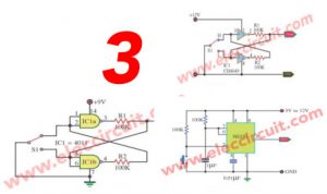
1.Random Number Generator circuit using IC-4017 and IC-4011
Firstly we see basic circuit before as Figure 1
This be Random Number Generator Circuit there is the character is 10 LED Flasher by use IC 4017 and IC 4011 integrated circuit. For the 4017 IC is a 16-pin CMOS decade counter. It takes clock pulses from the clock input, and makes one of the ten outputs come on in sequence each time a clock pulse arrives. Usability press S1 forLED Flasher respectively. By pressure (Close) S1 make LED all stick dim (Dimly).
When liberate (open) S1 make LED stick bright at LED any one to one’s fate. Besides value expansion C1 be 4.7uF make LED flasher slow down. The detail is other invite friends see in the circuit leisurely
.
Random Number Generator circuit using IC-4017 and IC-4011
This circuit is worked as video below you can change C1-470pF,1uF,10uF or others. And IC-4017, you can TC4017,CD4017,MC14017,etc.
Read also: DIY Flashing Bicycle LED Taillight Circuit
2. The 10 LED roulette circuit using IC-4017 and IC-4011
In Figure 2 is the 10 LED roulette that a game of my son.
How it works
When entering the power supply circuit, and switch S1 (Start), which is attached press release switch off. Then the current is flowing through R1, R2, and C2.
Makes the capacitor C2 caused up When the switch S1 allows the C2 to discharge through R3. The pressure this causes the clock input to the pin 8 of IC1a.
The IC1a which will work with production IC1b frequency to send it to the leg 14 (Clock) Of IC2.The IC2 is a driver by ICs LED 10 is illuminated by the moon to the incoming frequency.
The IC1d the IC1c and work together. It will serve up audio frequency generator, and then sent to the Piano Society (PZ1) loud beep came out with the LED light period.
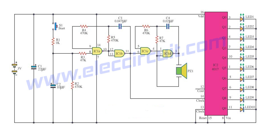
The 10 LED roulette circuit using IC-4017 and IC-4011
The parts list
IC1: CD4011, Quad 2-Input NOR Buffered B Series Gate
IC2: CD4017, Decade counter with 10 decoded outputs IC
C1: 1nF 63V Polyester Capacitor
C1: 22µF 25V Electrolytic Capacitors
C2: 10µF 25V Electrolytic Capacitors
C3: 0.047µF 63V Polyester Capacitor
C4: 0.022µF 63V Polyester Capacitor
R1,R2,R4,R5,R6: 470K 1/4W Resistors
R3,R7: 47K 1/4W Resistors
LED1-LED10: LED as you like.
Keep reading: ‘LED Chaser circuit’ »
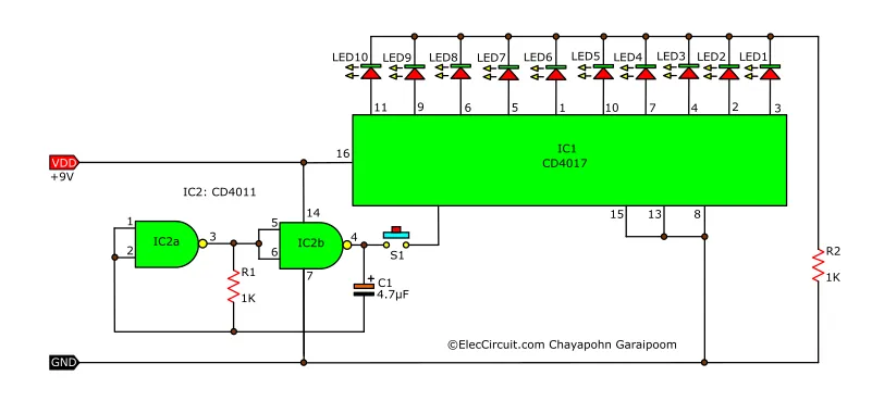
Mini LED roulette game circuit using Digital IC
This is Mini LED roulette game circuit using Digital IC, so simple and easy to builds, using IC-4017 to drive LED1-LED10, IC-4011 is oscillator, IC-4013…
When the switch S1 the output at pin 1 of the IC1a the voltage is “high”,The oscillator circuit output IC2b, IC2c work.Clock pulse generator fed to IC3, a voltage “high” output to the output pins 3, 11, and pin 12 of the IC3, the LED1-LED10 light chase sequence. Section LED11 show high – low point. The output of pin 3, 2, 4, 7, 10, of IC3 represented by high points,Output pins 1, 5, 6, 9, 11 instead of the IC3 with the low points.The jackpot for the LED12.The IC1b, IC2a and IC2d as controls.
Resistor R2 and capacitor C1 determine the period of the output “high” output from pin 1 of the IC1a. The capacitor C1 through R2. When you press the switch and the voltage drop across C1 will gradually increase until the maximum level. It will reset the flip flop IC1a become the output at pin 1 is “low”. And the oscillator output circuit to stop working, but there are some LED lights are pending, it may be that we end up being the LED.
So do not worry, it will switch a few times.Because, given a time period that the R2 and C1. The devices are required to keep a 6-volt power supply. If changed is 9 volts, must try for security reasons.
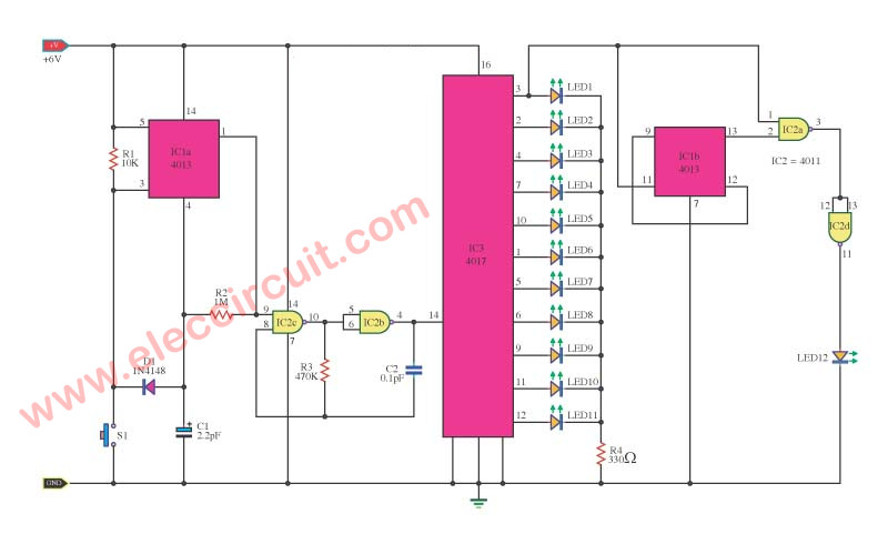
Figure 1 Mini roulette system circuit
How to build this projects
This project is not used many components so can assemble on the universal PCB board. as Figure 2 The wiring look out carefully for the polarity of the electrolytic capacitors and Diodes and LED and Pin of the ICs correctly.
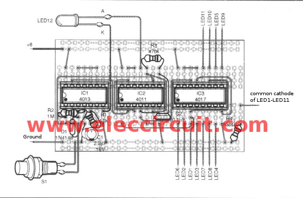
Figure 2 The components layout of this projects
Components lists
Resistors size ¼W +5%
R1: 10K
R2: 1M
R3: 470K
R4: 330K
Capacitors
C1: 2.2uF 16V, Electrolytic
C2: 0.1uF 50V, Polyester
Semiconductor
D1: 1N4001, 1A 50V Diode
LED1-LED12: LED Many colors
IC1: CD4013, CMOS DUAL D-TYPE FLIP-FLOP
IC2: CD4011, Quad 2-Input NOR Buffered B Series Gate
IC2: CD4017, Decade counter with 10 decoded outputs IC
Other
S1: Normally open pushbutton
The universal PCB board, 1 pcs.

I love electronics. I have been learning about them through creating simple electronic circuits or small projects. And now I am also having my children do the same. Nevertheless, I hope you found the experiences we shared on this site useful and fulfilling.