This is a morning sun alarm circuit using IC-4011. We make in hobby time or toys for my son. But really uses.
It has a sound alarm when morning like a normal clock alarm. But it uses a lighting sensor(LDR) to detect the sunlight.
And, we use an IC-4011 CMOS only one and a few components. To generate a pulsating tone like a general clock.
How This Circuit works
As Figure 1, this circuit uses the IC-4011 quad NAND gate as main of the circuit. It includes for a separate positive logic NAND gate on a single silicon chip.
Recommended: Simple IC 4011 LED flasher circuit
The in-circuit diagram consists of an oscillator circuit in an astable multivibrator 2 set.
First, set include IC1a and IC1b. Then, the second set includes of IC1c and IC1d.
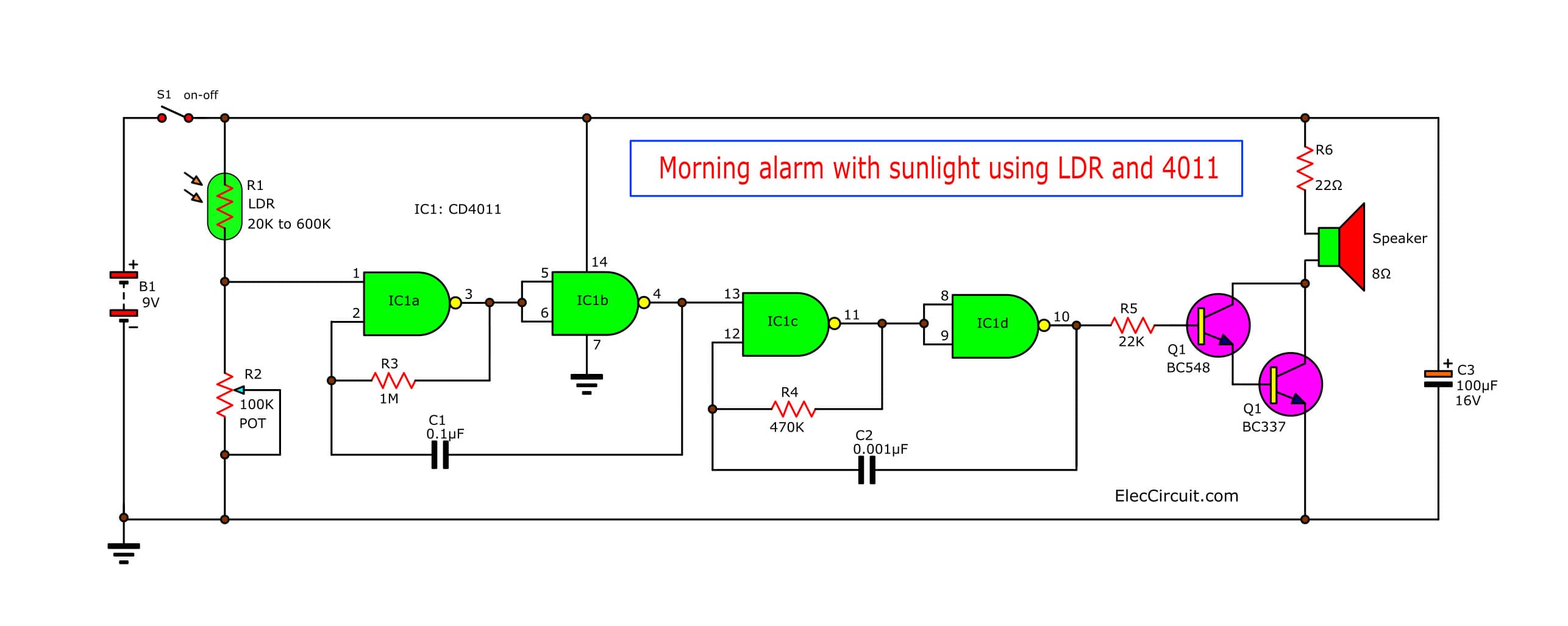
Figure 1 is a completely morning alarm with sunlight.
An R1 is LDR (Light Depended Resistor) or photoresistor which is a resistor type.
The resistance of a photoresistor changes with the light intensity to strike them.
If no light strikes it.
This resistor R1 may have high resistance rises between 500K to 600K. And if have normal light (Common Fluorescent light.)
The resistance will reduce is about 20K – 30K.
On the condition that LDR is getting light, because of its high resistance to more than the value of R2.
Read next: Simple Refrigerator Door Alarm circuit
The voltage at pin 1 of IC1a will lower half of the power supply. This causes the first oscillator does not work.
So, the second oscillator also not works. Therefore without a sound out of the speaker.
When LDR gets light. Its resistance will reduce. And the voltage drop across it will reduce. Making voltage across R2 rises unless more than half of the power supply.
Clock Tone Generator using 4011
It causes the first oscillator working to generate the output frequency.
So this frequency can determine with Resistor R1 and Capacitors C1
Frequency output:
F = 1/(2.2R1C1)
Which we use a value of R1 and C1 as the circuit above. It will get a frequency of about 4 Hz. At the same time, the output of IC1b states of “1”.
Related: 4011 Tone Generator circuit projects
So, it will cause the second oscillator (include with IC1c, IC1d, and R4, C2) has a frequency of about 900 Hz.
And if the output of IC1b states “0”, then the second oscillator will not works. The output of IC1d is the tone signal in Figure 2.
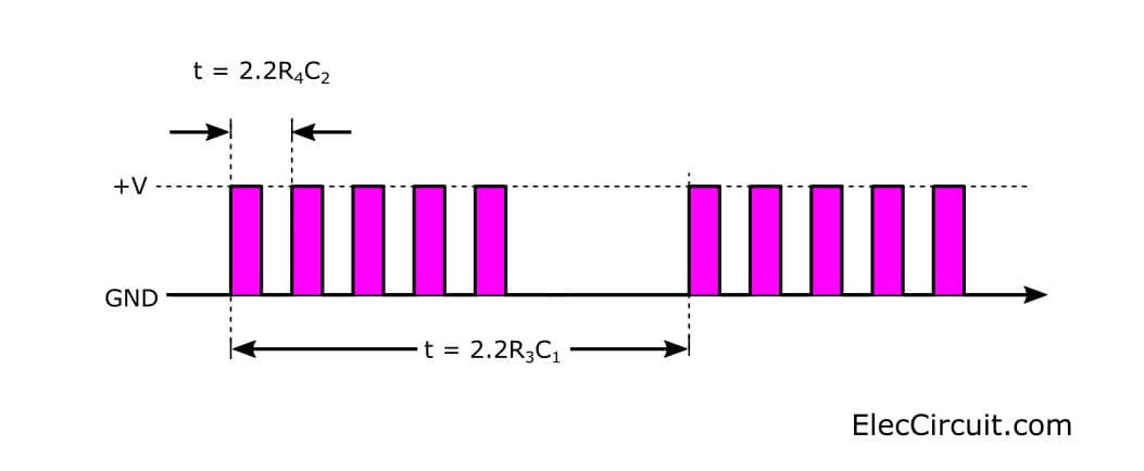
Figure 2 the tone burst signal characteristics.
The transistor-Q1 (BC547) and Q2 (BC337) are connected as Darlington compounds to increase the current up.
Read first for beginners: How do transistor circuits work
The resistor-R4 will reduce slightly volume of the speaker. If you want to high volume sound you need to change value lower.
The capacitor – C3 (100uF 16V) across between positive and ground of circuit. Which acts as filter the pulsating voltage into a steady direct current.
Read Also: Sound effect generator circuit using CD4040
How to builds and application
We can build this project easily, by solder all components on the perforated board and wiring as Figure 3.
Then, you may install them in the universal box. We drill aperture for LDR and potentiometer to adjust easily light sensitivity.
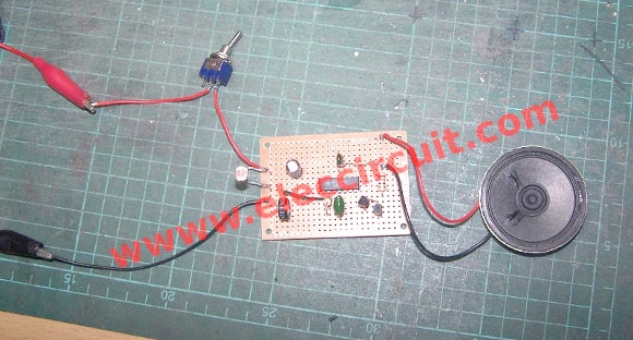
Figure 3
When we will assemble completely this project. Check for errors. Next, it turns On to apply the circuit. And then move LDR to light. We will hear the alarm sound out of the speaker.
Next, Use your hands to shade the photoresistor. It causes a sound stop. And we can adjust R2 to set the light sensitivity of the circuit.
That meaning that we can set them to begin working at any light as we need.
Note: PCB copper layout
If you want to assemble the device into a normal PCB. See the image below. Actual-size, Single-sided PCB for a Morning sun alarm circuit. And Component layout for the PCB.
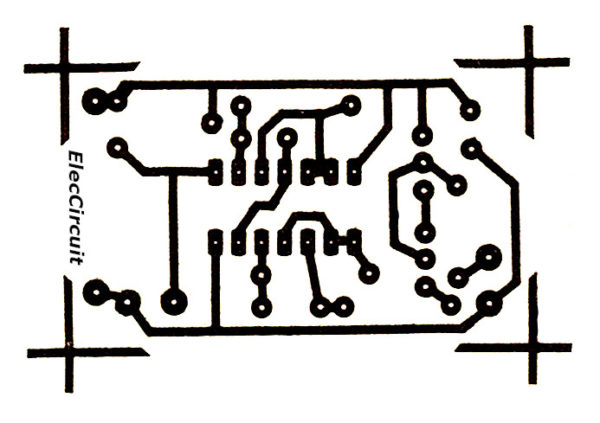
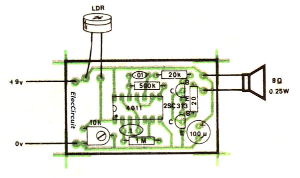
But Q1 is 2SC458 or 2SC1815 and Q2 is 2SC383. Both transistor pinouts are different from BC547 and BC337. Please be careful.
As the video below we test this in real uses.
The components List
Resistors ¼ watts 5% (unless otherwise specified.)
R1: LDR (change value in a range of 20K-600K)
R2: VR 100K, Trimmer Cermet or Carbon
R3: 1M
R4: 500K
R5: 20K
R6: 20Ω
Capacitors
C1: 0.1μF 50V, Mylar
C2: 0.001μF 50V, Mylar
C3: 100μF 16V, Electrolytic
Semiconductors
Q1: BC547
Q2: BC337
IC1: CD4011 NAND gate CMOS
Others
9-volts battery within the snap connector.
On/Off switches.
Speaker 8 ohms 0.5 watts
Wires, and others, etc.
Check out these related articles, too:
- Simple Light Detector Alarm with solar sensor
- 8 Light sensor alarm or Sensitive Sound Generator
- Light Actuated Relay Circuit using Photo Transistor
Related Posts


I love electronics. I have been learning about them through creating simple electronic circuits or small projects. And now I am also having my children do the same. Nevertheless, I hope you found the experiences we shared on this site useful and fulfilling.
Good circuit for me I will make it.
You got to push it-this esitaesnl info that is!
This circuit will not work if the capacitor is only 0.1Mfd and not 0.1 Mfd 50V Mylar capacitor. The resistance in the photo are only three and the resistance color code is not matching with the resistance used in the photo
Hai..
Really very appreciative project…
great circuit with 1 nand gate
Hi my friend
Thanks for your feedback.
Is that working…