There are many ways to make a CD4011 oscillator circuit. It is a digital CMOS 4011 quad NAND gate. I often use it. Because of the small, wide voltage supply range, easy and cheap.

Simple Tone Generator Circuit
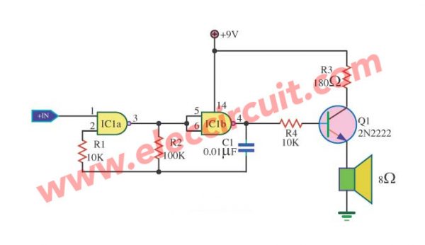
This is another circuit that uses a 4011 NAND gate for the pulse oscillator generator, which will output a 1.3 kHz tone.
We set the IC 4011’s input pin 1 for the control output tone generator. If a logic “low” does not have a tone, but a logic “HI” has a tone sound at a speaker.
The transistor provides a drive for the 8-ohm speaker.
The capacitor C1 is determined by the tone frequency rate.
And the resistor R3 controls the sound volume. If it is less than 180 ohms, it will be quite loud, but Q1 is too hot (high current).
R1 protects against overvoltage of the power supply, which may cause the input of the IC to be damaged. Normally, it is approximately 10 times the R2.
CD4011 Inverter Circuit
We use a simple tone generator circuit in many projects.
I like to use an inverter logic gate since it is easy and cheap. But we do not use it directly.
I mostly use IC-4011 NAND gates since they include four separate logic NAND gates on a single chip. It is enough for general usage, and it is quite cheap too.
We can use it instead of the inverter gates with connected input together, which have the same IC-4001 quad NOR gate, as illustrated.
Simple CD4011 oscillator circuit working
In any circuit, both analog and digital, an oscillation is generated with feedback.
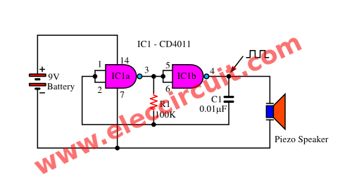
In this case, we also use R1 and C1 to feedback current output to input, causing oscillation.
As illustrated above, a simple tone generator using CD4011
To understand the function of this circuit, please read below by following these steps:
- We assume the output of IC1a, or pin 3, has a logic of “1”.
- So the output of IC1b, or pin 4, is “0”.
- Then, the voltage at pin 3 will begin charging C1 through R1.
- But C1 is also connected to the input of gate 1.
- Eventually, the charging C1 will become “1” enough to switch the output of IC1a from “1” to “0” logic.
- This causes IC1b to change states, and its output goes to “1.”.
- Now C1 is discharged by the output of IC1b.
- Eventually, the voltage at C1 and R1 becomes so “0”, that IC1a is switched back to the before state.
- Then it will go back and go on a cycle to continue.
If we reduce the supply voltage, it lowers the volume output.
Which we can use between 3V and 15V.
We should connect to ground the unused IC-4011 input (Pins 8, 9, 12, and 13).
How to assemble a circuit.
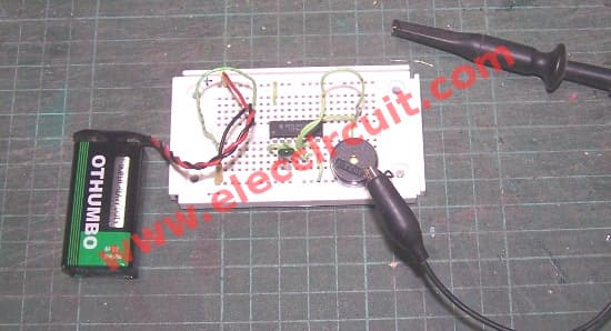
I assembled this circuit on a breadboard, as shown below. Then, check for errors and be sure the leads of C1 and R1 do not touch.
We can find the Frequency output = 2.2 R1xC1
R1= 100K
C1 = 0.01uF
= 2.2KHZ
See on Scope panel.
Then apply a 9-volt battery to the circuit. The piezo speaker should emit a tone. As the video below.
4011 Louder buzzer circuit using two transistors
Here is a Simple Continuity Tester circuit using IC-4011. If you are looking for a simple project for kids to learn oscillators on digital.
This is a tool for checking wires or some parts such as coils, PCBs, speakers, and more.
Is it good or bad? in easy to use.
If it is good, you will hear sound on the speaker. On the other hand, NO sound if it is lost.
How it works
In the circuit, it uses the integrated circuit, NAND gate CMOS, CD4011 as the main component. The IC1a and IC1b are working like an inverter (not) gate.
They have a few parts, R1, C1, and VR1 are a square wave oscillator to generate a tone. Then, this signal comes to the power amplifier (which compose a Complementary pair of transistors) to a coupling capacitor-C1. And to drive a louder tone on loudspeaker that. The frequency of tone can control with the 10K potentiometer.
How to use it
We may have 2 ideas to use it. First, Simple Continuity Tester! When you take a 9V battery to the circuit, do not need to use S1.
You use two probes to check many parts. It is suitable for wires and PCBs. Second, Moss Code Generator! Many Kids may use it for learning moss code in simple.
In addition, we need to connect the input of the other—does not use of IC1—to the ground or negative supply. To prevent all noise.
Resonance generators using 4011 CMOS Gate
This Resonance generator (oscillating sound generator) circuit. We designed it using CMOS integrated circuit, 4011(CMOS Quad 2-Input NAND Gate).

It contains within 4 NAND gate. Each oscillator circuit has a 2 circuit. This circuit provides a higher frequency, IC1c, and includes IC1d. Another one, the frequency range below and include IC1a IC1b.
The low-frequency pulse is sent to control the work of another. Diode D1 will IC1c and IC1d a pulse out at low frequencies. The diode D2 will cause the oscillating sound. S1 open voting is oscillating slowly lowered slowly. The discharge of the capacitor C1 value of the equipment does not need to be very accurate. SP1 except that it must be a transducer crystal.
Simple Clock Sound Effect circuit using IC4011
This is the simple clock sound effect circuit using IC4011 NAND gate digital CMOS IC for oscillator as tone generator. Then to transistor driver to output audio transformer to the speaker.
The sound of insects such as crickets, cicadas, resulting from flutter briefly. We can use a multivibrator to connects as sound generator circuit to imitate these insects sound.
Some electronic clock alarm tone also sounds similar to these insects. As Figure 1 is simple clock alarm sound generator that can assemble on a breadboard right away.
Working of circuits
As Figure 1 The circuit consists of two astable multivibrators, firstly include both gate IC1c and IC1d are used to generate low frequency as the sounds of insect wings. A second also includes with both gate IC1a and IC1b same simple tone generator using CD4011 which is higher frequency than first. And they are used to set rhythm intervals of sound.
The output of multivibrator 2 (pin 4 of gate I2) will be controlled by the first astable multivibrator which generates the low frequency as the tone burst signal characteristics.
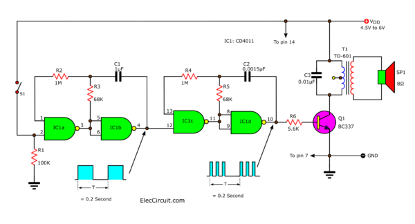
Figure 1
We control them to switch continuously with oscillation and stop oscillation with a low frequency of about 5 Hz.
In this case we use signal “1” and “0” alternately. If state “1” will make the oscillation, but is “0” will stop the oscillation.
The Devices R and C the astable multivibrator as circuit will get tone frequency about 600 Hz and Strokes will interval is about 0.2 Second. Please try modifying these to change the R and C melodic sound to listen up.
Components list
IC1: CD4011, Quad NAND gate CMOS
Q1: BC337, 0.8A 40V NPN transistor
T1: Small signal transformer
0.25W Resistors, tolerance: 5%
R1: 100K
R2, R4: 1M
R3, R5: 68K
R6: 5.6K
Ceramic Capacitors
C1: 1uF 50V
C2: 0.0015uF 50V
C3: 0.01uF 50V
SP1: Speaker 8 ohms
9V power supply circuit
How to build
We experiment the circuit on a breadboard or assemble all components on Perforated board as Figure 2
The previous circuit low volume since the piezo speaker which uses high impedance so use low current consumption, but its low volume.
This circuit I need loud volume better than the previous circuit. So use normal speaker 8 ohms 0.25 watt. But we cannot connect it to IC’s output directly.
We use a small audio transformer to prevents the very low resistance of the speaker (8 ohms) from loading down the circuit and possibly even stopping its oscillation.
And there is transistor-BC337 to drive transformer, cause this circuit to have a very loud volume than one.
Switch S1 is used for turn ON/OFF tone generator.
The power supply voltage can use during 4.5V to 13V, This reduces the supply voltage and lowers the volume. As the video below.
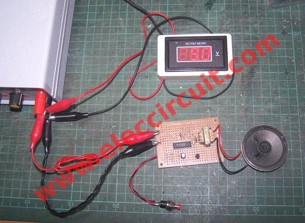
Simple Sound Alarm Generator using CD4011
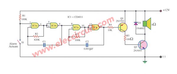
This is Music Sound Generator circuit. It is a basic and simple circuit. By using integrated circuit digital number CD4011 or MC14011 or TC14011.
It is NAND gate logic. By three this circuit is giving can the sound about 10watt by use 8ohm loudspeakers and use power supply voltage 12V.
Friends can lead this circuit into pieces warn have a voice loud periodically. By control on-off, the sound has with SW1 or Alarm Actuate Switch. The detail is other a friend sees in the circuit.
Easy sound Generator high power using TC4011
Origin sound circuit or sound Generator model this to receive design give can go out 10watt with full speed from ahead power supply 15volt. Besides still sound origin periodically as well.
Which if lead this circuit goes to assemble with the circuit steal already it will give the sound that attracts more than the loud ordinary sound.
The work of the circuit use switch S1 is formed control. Integrated circuit IC1 at using the number TC4011, which assemble be NAND Gate 2 input 4pcs.
Tempo tap circuit using CD4011
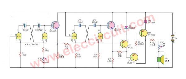
This Tempo tap circuit will have an effect than Tap the rhythm circuit other because the whistle is giddy, which vividly than usual knock. You can also adjust the speed with 10-40 strokes per minute.
Operation of the circuit
We will divide this circuit into three main parts of the schedule, the frequency generator, the control and amplify signals. The timing is IC1a, IC1b is a device to build up the frequency.
This frequency is determined by R1, R2, C1, C2 and VR1. VR1 will be controlled by frequency And the frequency will be set of Q1, which works to affect Q3 Q1 Q3 to work intermittently The frequency generator is IC1c, IC1d frequency generator to drive out to the speakers.
The frequency determined by the C3, C4, R5 and R6 signal will be expanded to drive the Q2 and Q4. But Q4 will not allow signals to pass the time. Q3 to control because it will work again in Q4. And Q5 connected with acts amplifiers to speaker, with a VR2 adjust the volume.
Parts you will need
0.25W Resistors, tolerance: 5%
- R1, R5, R6: 10M
- R2: 100K
- R3,R10: 47 ohms
- R4, R8: 10K
- R7: 4.7K
- R9: 680 ohms
- VR1: 1M, Potentiometer
- VR2: 47 ohms, Potentiometer
Capacitors
- C1: 2.2uF 16V Electrolytic
- C2: 0.027uF 50V Ceramic
- C3, C4: 180pF 50V Ceramic
Semiconductors and others
- D1: 1N4148, 75V 150mA Diodes
- D2: 1N4004, 200V 1A Diodes
- Q1, Q2: BC547 equivalent, 45V 100mA NPN Transistor
- Q3, Q4: BC557 equivalent, 45V 100mA PNP Transistor
- Q5: 2N2905, equivalent, 40V 0.5A NPN Transistor
- IC1: CD4011, MC14011, NAND GATE CMOS
- SP1: 8 ohms Speaker
- B1: 9V battery Or 9V power supply circuit
GET UPDATE VIA EMAIL
I always try to make Electronics Learning Easy.
Related Posts

I love electronics. I have been learning about them through creating simple electronic circuits or small projects. And now I am also having my children do the same. Nevertheless, I hope you found the experiences we shared on this site useful and fulfilling.





I need a small 4, 6, 9 or 12 VDC tone generator for a large scale model warship’s fog horn – 80Hz – 100Hz. O can add and amplifier if needed. Can any of the your circuits be modified for 80HZ, if so which and how? Or perhaps you can suggest something else” it doesn’t have to be a schematic or kit, a turnkey unit will work?
Thanks
“Simple CD4011 oscillator circuit working” there is NO component C2.
C1 is the timing cacpacitor.
There is no explanation as to why the previous circuit had a 10K resistor in IC1a input, but it is directly connected on this version of the circuit?
Hi,
Thanks for your visit. You are correct, we just edited it.
I’m just about to learn this IC number. It’s very interesting. 🙂