Are you happy to learn electronic circuits? I am going to show you, simple light detector alarm circuit.
Imagine, weak sunlight in the morning. The light makes the circuit runs. Noise you! You can’t bear to hear its alarm.
Have ever you try a light detector? I like to test those circuits. How is this circuit different from other circuits?
Related: Making Simple Light-activated relay circuit with PCB
We improve this circuit a whole new to higher efficiency. At the same time, it is cheaper. Because of:
- Cut VR-potentiometer (horseshoe-shaped resistor) take away. No need to make any adjustments
- Use a solar cell instead of LDR. It will reduce complexity.
- Use simple transistors without any ICs.
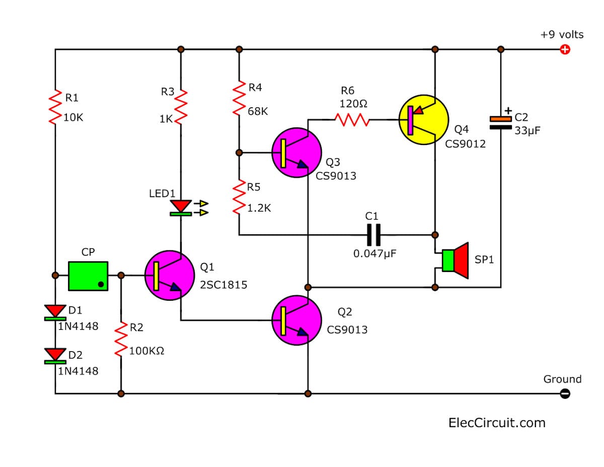
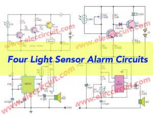
Figure 1 Simple Light Detector Alarm with solar sensor
Recommended: Learn Electronics with easy steps!
The difference between LDR and solar cell
- LDR
They will have a high resistance to the electrical current when in dark. And will has lower resistance when the light drop on it. - Solar cells
They have a feature of the high-value resistor when in the dark. But when it gets light, it will produce a certain amount of electrical current. Which depends on the brightness of the light over them.
What is more?
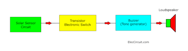
Figure 2: Block diagram of Simple Light Detector Alarm with solar sensor
Read first for beginners: How do transistor circuits work
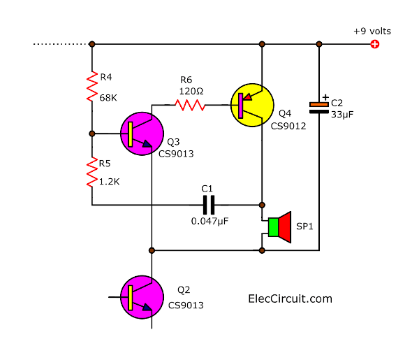
In the tone generator or buzzer sound. We want a more loud sound output. So, we should use a new form with matching pair transistors.
Which, It can provide the signal very stronger than a general.
There is an LED to show the condition of the circuit as well.
How this circuit works
Look at in the circuit, Figure 1.
How we can understand it easily? Here is step by step a process.
First, look at a tone generator (buzzer) section.
We use matched pair transistors number CS 9012 and CS 9013 to connected together with resistors of 3 pcs and one of the capacitors.
They are the sound signal generator circuit at the frequency of about 1,220 Hz.
And, at a common point of this circuit will be connected to the collector of transistor-Q2.
In this look. If Q2 does not conduct. No current to cause the buzzer generator section runs.
And in this section, the base of transistors-Q2 will be connected to the emitter of E of Q1. Which we called that Darlington compound. They have the gain of the current is very high.
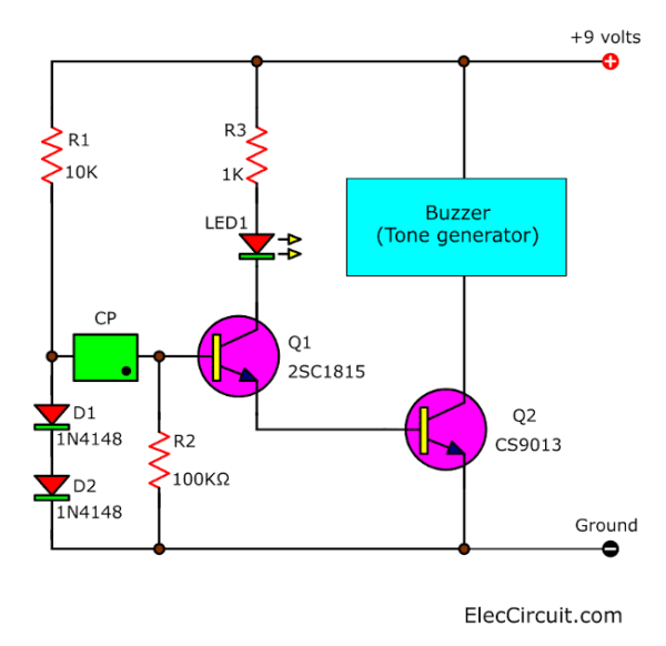
The connecting that at pin B of Q1. When compared with the ground need to have voltage to it exceeds 1.2V.
Thus, we connect the positive of the solar cell to base of Q1. And, connect the negative of the solar cell to a dividing point between Resistors-10K and two diodes.
At this point, we connect the diodes in the forward bias. Use 2 diodes in series. So, the voltage drop across the diode, about 1.2 V.
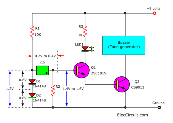
While the solar cells have not been lighting. At pin B of Q1. No current will flow. The voltage of the diodes is not enough.
However, when the solar cells are light. It will create a certain amount of voltage to about 200-400 mV. Which, depending on the brightness of the light.
And, this voltage will be connected series with the voltage of the diode. Therefore the voltage so equal to about 1.4V to 1.6V.
Which this is enough to make the Q1 and Q2 conduct current, and has Audio signal out to the speakers.
The LED is connected to pin C of Q1. It will glow when Q1 conducts. Or while there is sound enough to indicate the condition of the circuit.
How to build this project
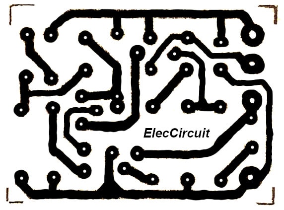
This project is used a few components. So, can assemble on the universal PCB board. But we can make a PCB. Then, the wiring for circuit wiring and various components can view of the example in single-sided PCB layout
And The components layout
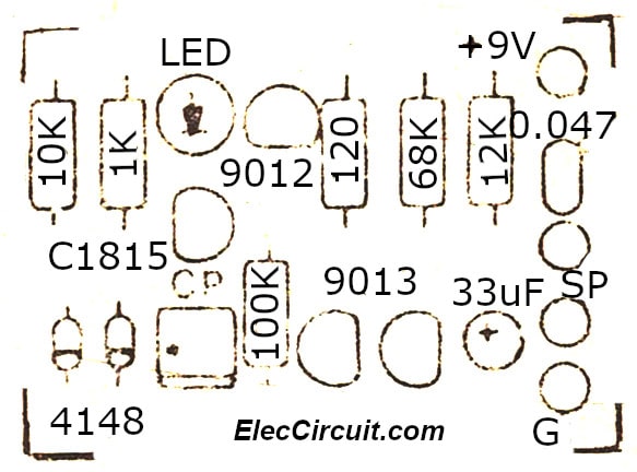
You are also must check carefully for the polarity of the solar cells, the electrolytic capacitors, diodes, transistors correctly.
This circuit uses 9 volts of power supply,9V battery. And all resistors in 1/4 watts, the speaker size as 2 inches 0.25W 8 ohms.
The components list
Q1: 2SC1815 or 2SC458, 45V 100mA NPN Transistor
Q2,Q3: CS9013, 50V 800mA NPN Transistor
Q4: CS9012, 50V 800mA PNP Transistor
D1,D2: 1N4148, 75V 150mA Diodes
CP: Solar cell, see in text.
C1: 0.047uF 50V, Ceramic Capacitor
C2: 33uF 16V, Electrolytic Capacitor
0.25W Resistors, tolerance: 5%
R1: 10K
R2: 100K
R3: 1K
R4: 68K
R5: 1.2K
R6: 120 ohms
9V power supply circuit
Even more importantly.
Look at: Morning sun alarm circuit using IC-4011
It is better with sound effects to look like a real alarm clock.
Not only that!
Check out these related articles, too:
- 8 Light sensor alarm or Sensitive Sound Generator
- Light sensor switch circuit using JK-Flip-Flop
- Automatic Night LED light switch circuit using solar rechargeable
GET UPDATE VIA EMAIL
I always try to make Electronics Learning Easy.
Related Posts


I love electronics. I have been learning about them through creating simple electronic circuits or small projects. And now I am also having my children do the same. Nevertheless, I hope you found the experiences we shared on this site useful and fulfilling.
sir,how can i charge 4.5 v battery using 6v or 8 v solar panel or charger