Today we will learn how to use the LM317 as a switch to turn the power load on and off. It still has the same protective properties. Even with higher frequencies.
It all started when Dave asked, “Will this work with a battery pack of 22vdc to provide 22vac at 60hz?” in the 60Hz clock pulse generator circuit.
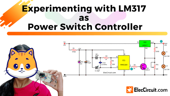
So I believe that solving this problem is a great opportunity for me to teach Chayaporn. We are going to learn about the LM317 power pulse generator. And I think you might find it useful to you as well.
The MM5369 CMOS, which we have used before, is often used as a precision time base when working with a quartz crystal and the RC network.
Normally, MM5369 requires a wide range of voltages (3V–15V). So, it definitely cannot be used with a 22V voltage level. And it outputs a very low current because it is a small IC focused on energy savings.
The concept of this circuit
Now let’s look at the block diagram of what we want to achieve. It will help us visualize the circuit idea we would need.
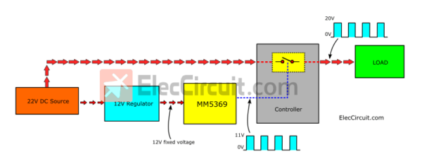
Each block can be divided into:
- 22V DC Source is the only power source in this circuit.
- The 12V Regulator will provide a constant 12 volts when powered by 22 volts. Because MM5369 requires a stable voltage power supply (12V fixed voltage).
- The MM5369 block is a 60 HZ pulse generator or time base.
- The controller acts like a general on-off switch. It will connect the high power from the DC source to the output by controlling the MM5369’s signal.
- A load is a device used to test the circuit. It is connected to the output and requires a high current.
The important point is that the output signal must have the same waveform as the MM5369’s signal. But it will also have a higher voltage level, from approximately 11V to 20V.
Choosing components
Next step: let’s choose components according to our specified requirements, such as performance, size, and price.
The 12V Regulator Block:
We use a Zener diode regulator to provide a stable 12V voltage. Since IC1 requires less current, a simple circuit like this is sufficient.
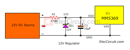
We can easily calculate the value of R1 by:
R1 = (Vin-Vic1)/ Iic1 = (22V-12V)/0.02 = 500
Vin = 22V, VIC1 = 12V, IIC1 = 0.02A
The watt rating of R1 doesn’t need more than 0.5 watts. Because the power (P=VxI) carries only 0.02A x 10V = 0.2 watts.
So, we use R1 is 470 ohms 0.5W
Also, we add C1 to add the efficiency of this circuit.
Controller Block:
The simplest and most popular method is a transistor. It is a good switch. We can use the low voltage level at the base to control the higher voltage load at the C-E, just like a relay. But it works much better at high frequencies.
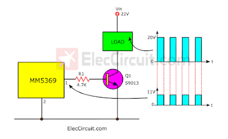
We tested with the S9013 NPN transistor. But it can only be used with a load that consumes no more than 0.2A. The signal shape at the output of IC1 and at the load remains the same, but with different amplitudes.
But when we want to use the load, that consumes more power. It is necessary to change the transistor to one that can withstand an increased current, such as BD139 or TIP41.
Using LM317 as a switch
But since we now have a lot of LM317 voltage regulators. They are highly efficient and quite cheap compared to a conventional TO-220 transistor.
So, it is great that we learn to use it more.
Looking at the Datasheet, the LM317 can accept a maximum voltage of 40V and a maximum output voltage of 37V, and a high output current of 1.5A.
But Interestingly, it has a good protection system when short circuit or overcurrent occurs.
Let’s do an experiment. In the circuit below, disconnect R2 and insert the S1-push button switch.
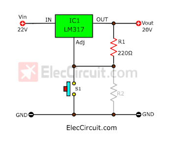
When S1 is not pressed, the output voltage is about 20V. But when we press S1, the voltage is reduced to about 1.2V.
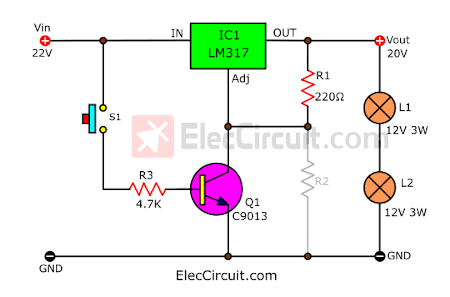
Then we changed the S1 position for Q1 to act as a switch instead. And move S1 and try pressing S1 again. To see the effect more clearly, we add a 24V 3W lamp as a load. (We use a 12V 3W bulb in series.)
When we release S1, both bulbs will light up, but when S1 is pressed, both bulbs will turn off normally.
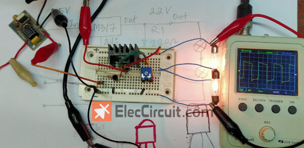
Next, let’s try putting all the parts together, turning it into a complete circuit.
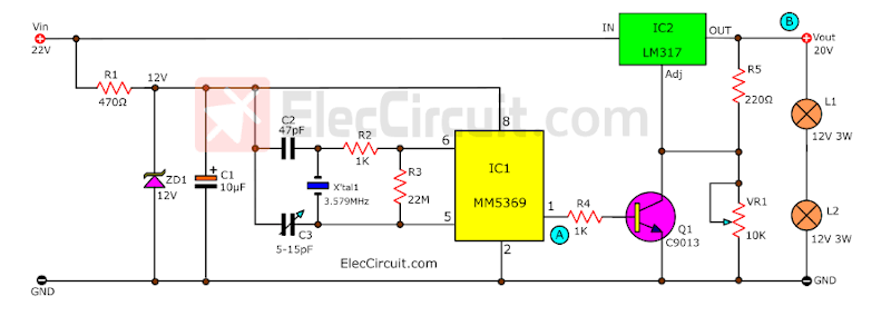
We will see light bulbs turned on. And the signal measured by an oscilloscope came out quite complete.
The signal at point A (the output of IC1) and point B (the output) has a phase difference of 180 degrees, or an inverted phase.
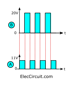
The output of an LM317 is 180 degrees out of phase with the input signal of an MM5369.
When changing the load to one that consumes more power, the LM317 still works normally. It can supply a maximum current of 1.5A. We can also adjust the amplitude of the output signal with VR1, such as to 15V or 18V, etc.
Conclusion
By solving this problem, we have used LM317. Which works well. Although it’s not perfect, But it helps us learn to use the LM317 more.
We are quite satisfied with the LM317 as a switch because it is very flexible.
But it has a few limitations:
The minimum voltage level is not 0V (but 1.2V).
When the frequency level is higher than 1kHz, the signal may be distorted.
There is always a loss level within the LM317. As seen in the experiment, if the input voltage system is 22V, the voltage that comes out will only be about 20V.
If you want to reduce this voltage loss, transistors should be used instead. But since we do not have this transistor yet, we cannot experiment with it right now. In the future, we would try it.
Get This
All full-size images and PDFs of this post are in this Ebook below. Please support me. 🙂
GET UPDATE VIA EMAIL
I always try to make Electronics Learning Easy.
Related Posts

I love electronics. I have been learning about them through creating simple electronic circuits or small projects. And now I am also having my children do the same. Nevertheless, I hope you found the experiences we shared on this site useful and fulfilling.