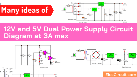
See the various concepts of 12V and 5V power supply circuit diagram. This circuit might ever make you headaches that unavailable or do not match the job.
But this article will help you save money. Also, It is great learning. To create a circuit by yourself.
All circuits are DC voltage regulator. So, you can trust them, low noise.
How to Choose a suitable Design Concept
We should answer ourselves that What is this circuit built for?
- 5 volts
When your load is a digital circuit of the TTL family or various microcontrollers. They only need a constant voltage level of 5V. So, we have to use a DC voltage regulator circuit.
When the current is less than 100mA. We may use the transistor and Zener regulator. (Easy and economical). But most if the current is less than 1A.
We often choose the IC-7805 regulator. Because it’s easy to find, cheap
- 12 volts
When we use general loads such as audio amplifier ICs, relay drive circuits, or even a CMOS digital chip. We can use a 12V power supply circuit.
We may use an unregulated power supply in some circuits that do not require high accuracy. Just have a small ripple voltage, such as a relay drive circuit.
If a circuit that requires a constant voltage level should be 12 volts regulator, too.
Do you get ideas? See the circuit below you will clearly understand.
Some want 9V power supply instead of a battery. It is a good idea because it is suitable for low current use.
12V & 5V @ 1A Power supply
Build CD-ROM Drive power supply circuit
If you have an old CD-ROM drive. It can play an audio CD alone, a great sound. But it requires a 12V 5V power supply circuit. We have many ways to builds DC power supply for the Audio CD-ROM player.
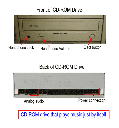
What is more? Let’s make a power supply for Our Music player.
12V 5V power supply circuit using 7805 and LM7812
Look at the circuit below. This can deliver DC voltage of 5V and 12V at 1A.

Since the CD-ROM drive is electronics part that required a regulated power supply. So, we use a 3-Terminal 1A fixed-voltage integrated circuit,7805 and 7812.
Learn more: 7805 regulator circuit datasheet
This circuit is a common Regulator power supply circuit that many people may have seen familiar.
The circuit consists of an unregulated and regulated supply IC7805-7812.
We will look at the unregulated supply first. They consist of important equipment such as transformers, Diodes Rectifier, and Capacitors filter.
Recommended:
How it works
Here is step by step a process.
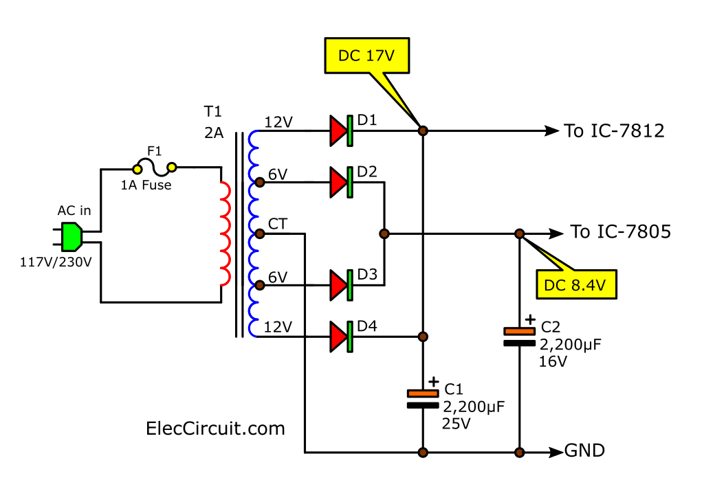
First, the AC main (230V/117V) passes into the circuit via F1. This is a simple device. It protects when the electric power is over.
Then, the step transformer converts the AC main to low voltage, 12V, 6V with CT. It determines the maximum current required. In this case, we need the output current 1A both 5V and 12V. Therefore, we should choose 2A transformer.
We set the circuit as a full-wave rectifier with helping of four didoes.
If you are a beginner, please read first:
Principle of unregulated power supply.
I don’t explain it to you now. Because it will make this article too long
Look at the short-form circuit diagram.
There are two sections.
- 5V Section
At 6V CT 6V, the D2 and D3 rectify AC 6V to DCV. Then C1 filter capacitor to pure DC. Also, C1 is important. We should use the right capacitance. If uses too lower, we will get low DC voltage and high ripple. Now the voltage across C1 is about 8.4V. - 12V Section
At 12V CT 12V, D1 and D4 rectify AC 12V to DCV and C2 smooth it to pure DC, too. But at C2 it has a voltage is 17V.
And Then, both voltages come to 7805 and 7812 regulator. To keep the output stable voltage are 5V and 12V at 1A.
C3 and C5 are filters, too. And C4 and C6 reduce the frequency disturbs or transient as well.
Parts you will need
D1,D2,D3,D4,D5: 1N4007, 1000V 1A Diodes
IC1: 7805, 5V 1A regulators IC
IC2: 7812, 12V 1A regulators IC
Electrolytic Capacitors
C1: 2,200uF 25V
C2: 2,200uF 16V
C3: 100uF 16V
C5: 100uF 25V
C4, C6: 0.1uF 50V Ceramic Capacitor
T1: 230V or 117 (as your country) AC primary to 12V,6V, CT @2A secondary transformer
F1: Fuse 1A
Recommended: Learning Electronics for beginners!
12V 2A and 5V Power supply circuit
If your load needs more streams. Such as car audio amplifiers It needs a supply voltage of 12V at 2A up. We can easily modify the circuit above.
Look at a new update circuit.
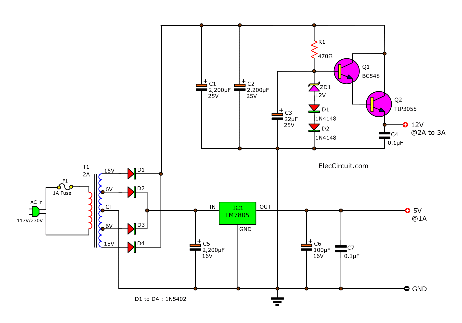
We still maintain the 5V power supply circuit. But change the 12V power supply circuit to become a transistor and Zener diodes Regulator version.
Even with more equipment. But not too difficult to understand.
We need the current more. We have to change the Diodes to 1N5402. It can connect the maximum current to 3A.
And, add another one capacitor C2 to increases the capacitance when has more current than 2 times. It make a more stable current.
Anyway, we see the circuit is a Transistor Series Voltage Regulator.
Learn more: Fixed Regulator using transistor and Zener diode
This circuit requires more input voltage, increasing efficiency. The voltage drop across C1 and C2 increases to 15Vx1.414 = 21V.
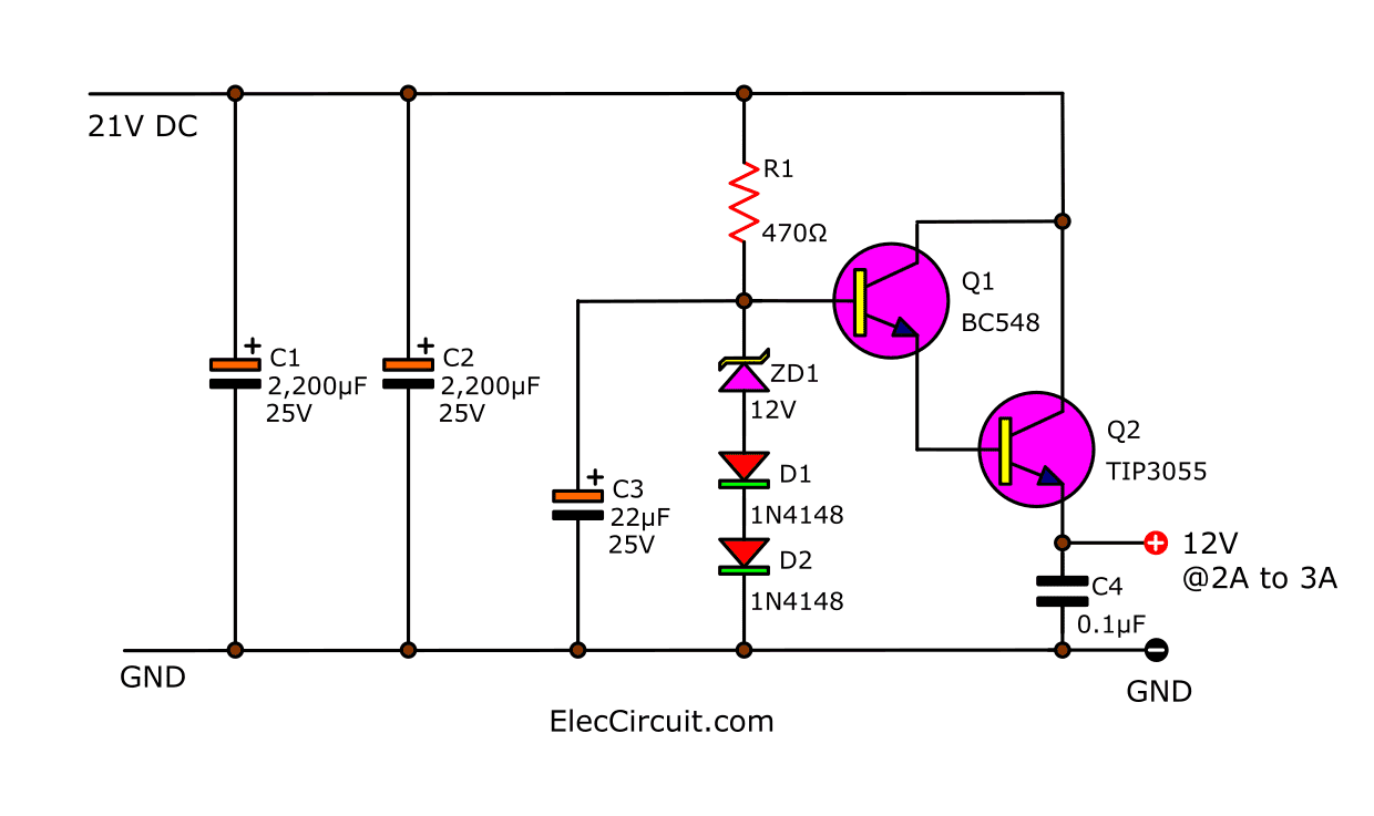
It’s better than before. We add the two transistors in Darlington(Q1, Q2) form to drive the higher current to 2A or 3A max.
The Zener diode is setting to keep the voltage fixed at 12V. And we add the two diodes to compensate for the voltage lost on the BE pin of each transistor (0.6V + 0.6V).
This causes the output voltage is 12V more precisely.
For other devices The original circuit is C4: the capacitor will filter any noise. The C3 reduces the ripple voltages.
Parts you will need
D1,D2,D3,D4,D5: 1N5402, 200V 3A Diodes
IC1: 7805, 5V 1A regulators IC
Q1: BC548, 45V 0.1A, NPN Transistor
Q2: TIP3055, 50V 15A, NPN Transistor
Electrolytic Capacitors
C1,C2: 2,200uF 25V
C5: 2,200uF 16V
C6: 100uF 16V
C3: 22uF 25V
C4, C7: 0.1uF 50V Ceramic Capacitor
R1: 470 ohms 0.25W Resistors, tolerance: 5%
T1: 230V or 117 (as your country) AC primary to 12V,6V, CT @2A secondary transformer
F1: Fuse 1A
12V 3A and 5V 2A Regulator circuit
Our friend (Suresh) wants a DC power supply of 12V and 5V at 2A. We have many ways to do it. But this circuit below may be a better choice.
We will slightly modify the circuit above.
- Change the size of the transformer to 3A.
- Maintain the equipment in the same way as 12V. But it still supplies current up to 3A.
- Add a power transistor, TIP2955 to help expand the current even higher.
Digital CMOS and TTL Power supply
Sometimes in our electronic circuits Use different voltage levels. Such as digital circuits that use both the IC family of TTL. Which only requires 5V power. Connects to the CMOS family of ICs, which uses 12V power.
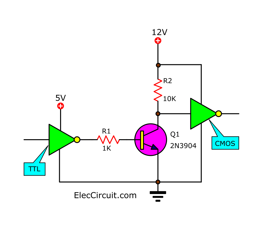
We can connect Both easily through the help of the transistor circuit above.
And we can use the power supply circuit for digital IC according to the circuit below
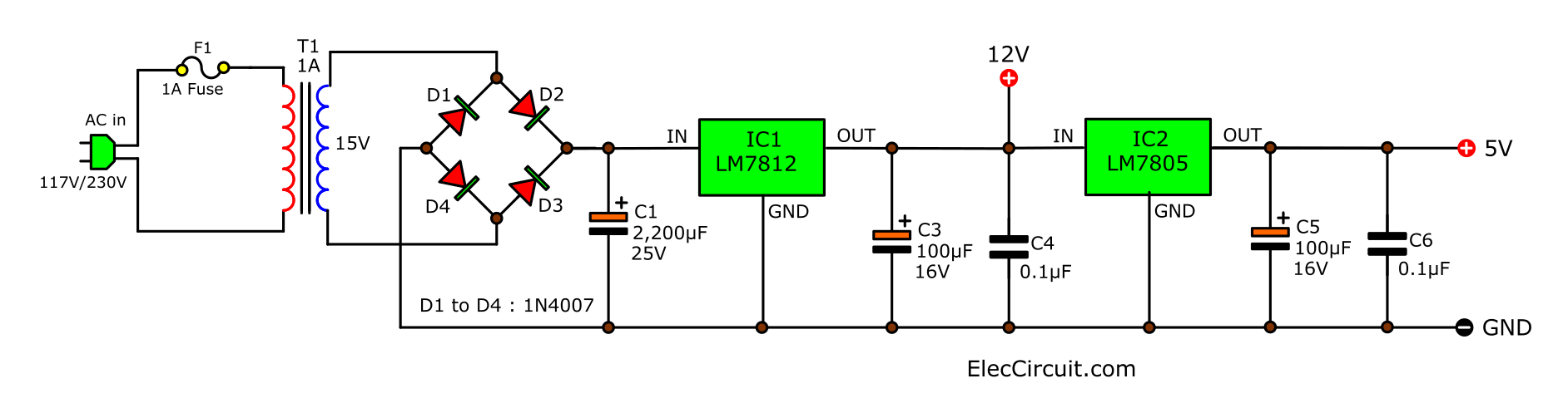
This circuit is modified from the circuit above. There are many points to consider.
- We use a 15V transformer with only one primary coil and therefore use a bridge rectifier circuit.
- Low output current no more than 1A which is enough for general digital circuits.
- Save the capacitor filter, but we get a 5V regulator with lower noise Because it receives the voltage from the 12V regulator.
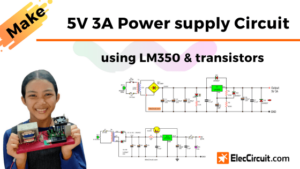
Recommended: 5V 3A Linear Power supply circuits You can build it!
Parts you will need
D1,D2,D3,D4,D5: 1N4007, 1000V 1A Diodes
IC1: 7812, 12V DC regulators IC
IC2: 7805, 5V DC regulators IC
Electrolytic Capacitors
C1: 2,200uF 25V
C3: 100uF 25V
C2,C4: 0.1uF 63V Polyester Capacitor
T1: 230V or 117V as your country, AC primary to 15V,1A secondary transformer
Also 5V 9V 12V power supply circuits
- +/- 5V and 12V Dual power supply circuit
- 15V Dual power supply circuit with PCB
- 7805 and 7905 Dual adjustable power supply project
- 0-60V Dual Variable power supply circuit using LM317-LM337
What’s more? You can look other power supply circuits: Click Here
Related Posts

I love electronics. I have been learning about them through creating simple electronic circuits or small projects. And now I am also having my children do the same. Nevertheless, I hope you found the experiences we shared on this site useful and fulfilling.
how much AMBER can i take or can i give me from this circuit?
12V~?A
5V~?A
Good Morning Sir,
I saw the circuits on tour website and I want to built, so Just to Know, How to buy the components to make the 2 circuits:
1)Convert Two level DC voltage 5V, 12V
2)Simple AC to DC converter 9V AC to 36V DC
Thank you
how many amps can the above circuit is
?
We need complete circuit diagram for in put ac 230 volt and out put DC 12vdc13.8vdc amp 15
And diode 2 and 3 what is the number of
470 micro F , may i know about the voltage?
How many ampere does it have?
in DC power supply 5V and 12V using 2N3055-LM309
I need 5v with 3.5A and 12v with 40mA
hallo Sir, i need from ac220v
to dc12v and 5v 2A output circuit diagram
Hi
Please read this article again.
I just add modified circuit. 12V 3A and 5V 2A power supply circuit.
How are the results? Please share your experience as well. Thank you.