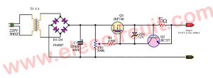
Many years ago, I built the first Variable power supply using LM317. Now, I have still used it. But if you need to use a 3A adjustable voltage regulator. This circuit is using LM317 with a pass transistor circuit for 5 important reasons.
First, it is a high-quality power supply. Second, the output current is up to 3A. Third, adjust the output voltage of 1.25V to 20V. Fourth, adjust the voltage in the step of 3V, 6V, 9V, 12V.
Finally, use a normal component, LM317, 2N3055, and more.
So, it is very easy to do.
Working of 3A Adjustable voltage regulator circuit
Output: 1.2V to 20V, and 3V,6V,9V,12V
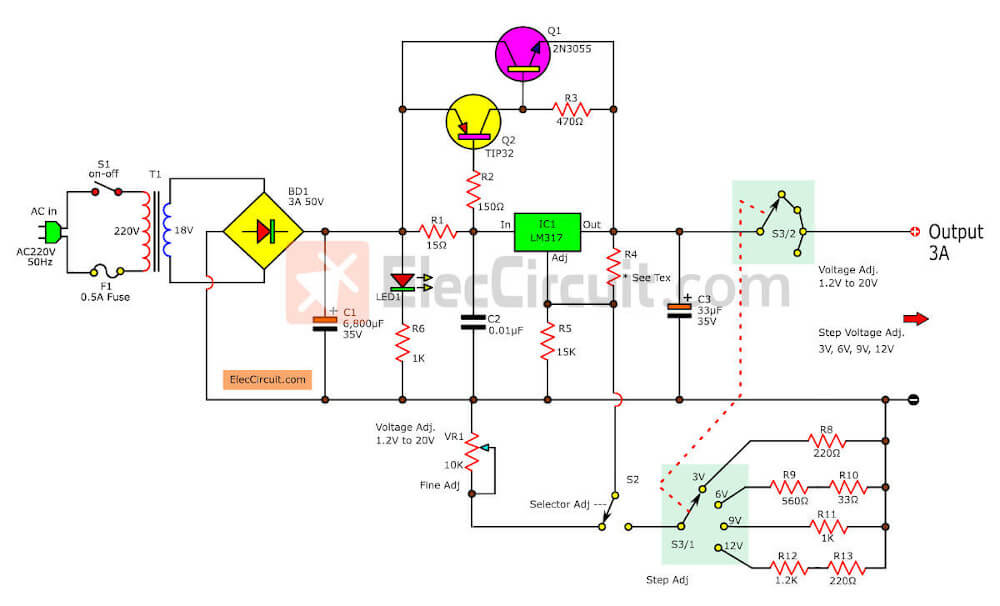
In the 3A adjustable voltage regulator circuit above.
First of all, get an AC main to the circuit. It comes to T1 through S1 and F1.
- S1—power switch to on-off.
- F1—0.5A fuse to protect the circuit when overcurrent.
- T1— The step-down transformer converts AC-main to the low ACV, 18V at 3A current.
Then, the AC18V comes to a diode bridge-BD1, to rectify ACV to DCV, pulsed DC.
Next, the capacitor-C1 filters which becomes the pulsed DC.
We called the unregulated supply.
While some current flows R6 and LED1. The LED1 shows power on. And the R6 limits the current to save LED1
Then, the unregulated voltage comes to an input of IC1 through R1. The IC1 is the main, DC variable voltage regulator IC, the famous LM317. It will make the output voltage is very steady.
Using 2N3055 as current boosting circuit for LM317
Above I said the circuit can power the 3A output current. But as we know LM317 can power out of 1.5A. What can we do? To increase it up! We help it with the transistors.
And R1 limits current to IC1. The voltage across R1 causes a current biased to Q2, driver transistor. R2 is a current limiting resistor of Q2.
When Q2 conducts, the high current will flow its collector and emitter to the base of Q1, the power transistor.
The Q1 is running because it gets a current bias, There is a voltage across R3.
Thus, the high power current will flow through the collector and emitter to the output, in the max current.
If you need a high current of the output. It depends on 3 important things:
- First, the current of the transformer.
- Second, the current of the diode bridge.
- Third, the capacitance of C1. It is enough.
Adjusting the output voltage
The circuit has two options you can choose.
- Fine mode
—When we switch the S2-selector to the fine mode. We can rotate the variable resistor-VR1 to change the output voltage, from about 1.25V to 20V.
If you do not understand clearly. Please back to see:
My first LM317 VariablPower Supply (1.2V to 30V at 1A)
- Stepping Mode
When we switch S2 to the step mode. We often use the same does not change For example 9V, and 12V to uses it instead of a battery. Thus this option is so good. You can rotate S3 to select voltage out of 3V, 6V, 9V, and 12V.
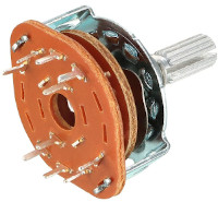
The S3 is a 2P4T 2 Pole 4 Position Rotary Switch Selector. We use this type of switch to reduce the problem of maximum output voltage. As we twist the voltage selector switch, S3/2 disconnects power from the output.
Read Also:
You can add more voltage range with some resistors at the S3.
See the feature like this circuit:
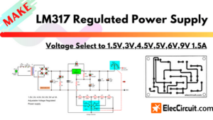
1.5V, 3V, 4.5V, 5V, 6V, 9V LM317 Selector Supply
The function of components
C2-filter capacitor eliminates the power spike voltage before comes to LM317.
C6-capacitor filters DC voltage to smooth better, low noise.
Components lists
Semiconductors
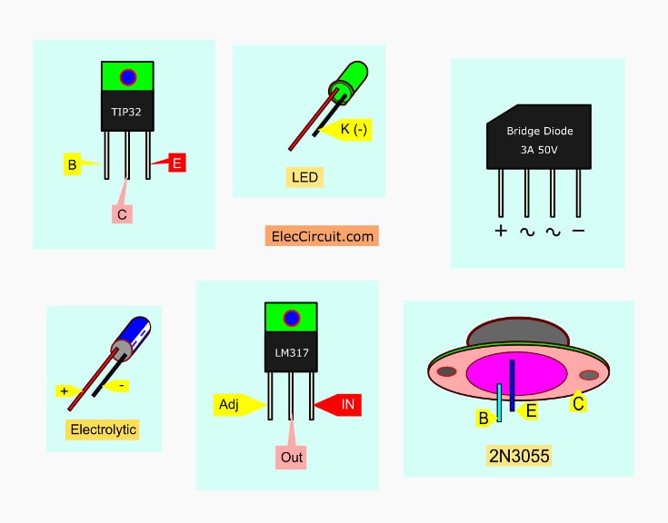
IC1: LM317T, 3 terminal positive adjustable regulator
Q1: 2N3055, 15A 60V NPN transistor.
Q2: TIP32, 4A, 60V PNP transistor.
Electrolytic capacitors
C1: 6,800µF 35V
C3: 33µF 35V
C2: 0.01µF 50V, Ceramic Capacitor.
R1: 15Ω, 1W Resistor.
Resistor 0.5W, tolerance: 5%
R2: 150Ω
R3: 470Ω
R4: 150Ω
R5: 15K
R6, R11: 1K
R8: 220Ω
R9: 560Ω
R10: 33Ω
R12: 1.2K
R12: 220Ω
T1: 3A, 18V transformer
LED1: color as you need
S1: Power switch
S2: SPDT switch
S3: Selector switch—see text
PCB, Heatsink, and others…
Build 3A adjustable voltage regulator
This project has a few parts. I may solder the components onto the perforated board. Place position equipment according to the circuit. Figure 2 the PCB layout.
And assemble all components as Figure 3.
The Q1 should be held on a large heat sink. It is very hot for use.
The switches are connected correctly.
If you are a beginner must check and check, before entering the power, should review several times. To prevent damage!
In particular, Position legs of diodes, electrolytic capacitors, transistors, IC1.
Learn more:
How 741 OP-AMP Power supply Work
More Power supply circuits
If something is not wrong, you will have the full power 3A, which is talented enough to, show you how. “I make with myself, have a proud and active needs, in save”.
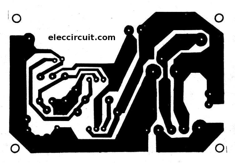
Figure 2: The PCB layout of the LM317 adjustable voltage regulator circuit
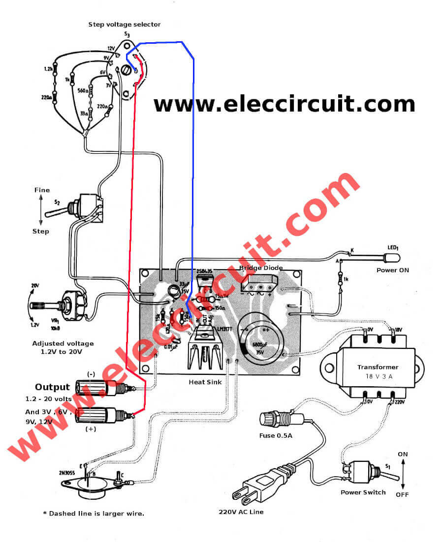
Figure 3: assemble all components layout to the PCB.
Be careful polarity component
Some components have the polarity. For example, electrolytic capacitors, diodes, LM317, LM337, etc. If you incorrect them. Your circuit does not work. Event them damage.
Also, LM317 adjustable voltage regulator
Also this project we can use LM350 to make 1.2V to 25V at 3A Adjustable Regulator instead. Thanks, Mr. OHM 1970 suggests that us just remove both transistors.
You may not like it. Because of large and expensive.
See the below circuits better!
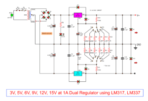
- 60V Dual Adjustable voltage regulator:
So well circuit, start voltage at zero voltage! and a higher maximum at 60 volts. - Dual power supply 3V,5V,6V,9V,12,15V
Selects volts easily. and cheap for all the jobs. - LM338, 5A Variable regulator :
Better life with high current in the same voltage 1.25V to 30V.
GET UPDATE VIA EMAIL
I always try to make Electronics Learning Easy.

I love electronics. I have been learning about them through creating simple electronic circuits or small projects. And now I am also having my children do the same. Nevertheless, I hope you found the experiences we shared on this site useful and fulfilling.
You can use LM350T and then you don’t need Q1 Q2 and it’s External Components,I Built this circuit Years ago with LM350T and it works Just Fine!!! This is a Great Design,,,, My idea is just a Suggestion,,More simpler for beginners(using the LM350T!!!)
Transistor Q2 2SB435 and also LM350 not available in my place. If you could tell me replacement part no. for Q2, really appreciated because I just wanted to build your circuit by myself. Thank you.
@Aung Soe Oo,,,Try E/BAY I’ve Seen LM350 there. And Then You don’t Need Q2( or Q1!!!) I like To Keep Things Simple,,Even Though This Is a GREAT DESIGN We Can Eliminate The Transistors And The associated Resistors …Just a Suggestion Here!!!
yes this circuit is very good and b435=bd244
Good Idea,Good circuit “Top”
pretty good idea
Hi,
Sorry, my electronic is basic.
My question:
How can we have 3 Amps, if LM317 outputis only 1.5 Amps????
Thanks
how can i make this power supply if the available transformer is 24V output only
very nice
Dear sir, if I want to build 30 A adjustable like on that schematic, what should I change. Please I need as soon as possible. I have tip2955 and tip3055.
Hi,agung Nugroho
Yes you can use TIP3055 instead 2N3055.
But I not sure about 30A adjustable power supply.
may connected them in parallel.
Sir Im from the Philippines can you make a simple and cheapest diagram of Power Supply 3v, 4.5v, 6v, 7.5v, 9v, 12v and 15v with 2 Ampere? Your response is very much appreciated. Thank you
Hi, John Sabalboro
Thanks for your feedback.
This circuit work well.
I’ve a PARALLEL CONNECTED 20V DC SUPPLY LED LIGHTING SYSTEM BUT I DON’T HAVE 20V POWER SUPPLY.IS THERE ANY POSSIBLE WAY TO DECREASE THE VOLTAGE OF THAT LIGHTING SYSTEM TO 10V… THANK YOU IN ADVANCE
Thanks for this great project, i try to build one for me..
Hi, prsanna
Thanks for your feedback.
Do you need to reduce voltage lamp to 10 voltage?
You may use dc to dc step up voltage to increase voltage to 20v.
https://www.eleccircuit.com/simple-dc-to-dc-step-up-converter-using-tda2822/
Or choose at https://www.eleccircuit.com/dc-converters/
Hi, Canal
Thanks for your feedback.
If you finish your project please share us.
Hi Sir,
I want to connect 24 V DC supply, is hit possible to work?
sir what is my transformer is 16volts only?
sir, what if my transformer is 16 volts?
we need 6volt fixed dc power suply for project….
hi sir, im from Philippines I build this circuit but its not running well. when I tried to change the connection of emitter and collector of 2N3055. to negative line its already working. is there something wrong with my circuit?
hello friends
Can any one explain what is the purpose of R5:15k resistor in the above circuit
R5 acts in parallel to the potentiometer or the step adjust resisters. At any time, if the output is connected to a load and you switch between step adjust to fine adjust, for a moment, the adjust pin will be floating. This shouldn’t happen. May be that’s why R5 is needed. It doesn’t affect the resistance as its very high and in parallel to the other resistors.
Hello Sir, could you send me the diagrams of the stabilized power supply of plus and minus – + 12, – + 15volt
C/o prakash sahu, sahu provison stores
Dr. dikshit gali, nandi chowk, tikrapara
can this circuit be used to charge as car battery charger (12V 30A) Lead acid battery too? if yes what would be rated voltage & current for charging a discharged battery?
Hi
This circuit is very useful and cheap
Thanks
Hi Man
Thanks for your feedback.
hello sir how can i change 3A to 5A output
TIP32____4A___60V PNP transistor. but it is available with 3A…..how?
Hello !
Very well-done and interesting stuff ! I like the way you explain electronics half way between theory and practical principles. Great ;). I’ve been electronician for a long time now (achieving my cursus on 2002 !), and it’s a good place to remember some of the most common circuits. Thank you !
Thank you for visiting our website. I’m very glad that our content is useful for you uncle.
I and my father will continue to do it. Uncle keeps coming in to follow. 🙂
Hello, a question, is the capacitor C1 six thousand eight hundred Farads or 6 point 8 Farads?
Hello,
Thank you very much for visiting our website.
It is a six thousand eight hundred microFarads.
I’m sorry to make you confused. 🙂
Appreciate the recommendation. Will try it out.
Hi,
My pleasure! My dad and I will focus on making the circuits better and better. But I learned electronics quite slowly, it was difficult for me. But I’ll keep trying slowly, I think I can do it. 🙂
Hi, could you add a circuit that will function as a variable current limiter on the version of the 3A output so that the power supply will be able to provide 1.2V to 30V and current from 0 to 3A?
At this time we do not have the circuit you are looking for.
In the future, we will test the circuits you want.
Hope you will continue to follow us.