We used to use voltage dividers very often. Why do we use them in circuits? And How to use it? Let me explain to you understand the voltage divider rule. And can calculate in a simple way.
Even, this is suitable for a beginner. Are you the pro? Sometimes, may forget some point that can help your project work well.
Are you ready?
Why use a voltage divider?
You try to imagine You need a voltage of 1V. But you have a 10V power supply. We have many options. But for the most part, we will choose the voltage divider.
Also: Learn Zener voltage regulator
It will provide a low voltage out of a higher supply voltage.
I am quite reliable. The most commonly used example is the Zener voltage regulator. Or the reference voltage generator for the amp circuit etc.
Some call the voltage divider circuit that the potential dividers. The name comes from the difference of the electric potential
What is a voltage divider?
First, see in the simple circuit diagram below. The basic voltage divider circuit consisting of two resistors (R1 and R2) is connected to the power supply (Vs).
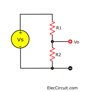
It looks like a series circuit.
Recommended: Learn series circuit works.
Then, the voltage from the power supply is divided between both resistors. It gives the output voltage (Vo). Which, is the voltage drop across the R2.
This voltage is dependent on the size of R2 and R1:
- If R2 is much smaller than R1
Vo will be small (very low, near 0V). Because of most of the voltage drop across R1. - If R2 is equal to R1.
Vo is equal to half of Vs. Because the voltage is divided equally between R1 and R2.
- If R2 is greater than R1.
Vo is very high, near to Vs. Because most of the voltage is across R2
Learn: How to use resistors
Voltage divider formula
If we want to know the output voltage (Vo) in detail. We can use Ohm’s law and mathematical knowledge.
Use the formula below. To calculate Vo.
Vo = (Vs x R2) / (R1+R2) ……..(#1)
From the above principles. Let’s test the truth with this formula.
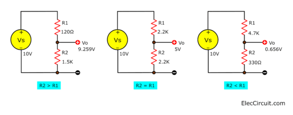
First, we use Vs = 10V. To easy to calculate. Then, test in 3 cases.
- R2 > R1.
Assigned to R2 = 1.5K (1,500 ohms), R1 = 120 ohms.
Vo = (10V x 1,500) / (1,500 + 120)
= 15,000 / 1,620
= 9.259V - R2 = R1
Assigned to R2 = 2.2K (2,200 ohms), R1 = 2.2K.
Vo = (10V x 2,200) / (2,200 + 2,200)
= 22,000 / 4,400
= 5V - R2 < R1
Assigned to R2 = 330 ohms, R1 = 4.7K(4,700 ohms)
Vo = (10V x 330) / (330 + 4,700)
= 3,300 / 5,030
= 0.656V
Do you see imagine? Look at circuit diagram below.
The limiting of voltage divider rule
We can use these formulas and approximation rules well. Only when ….The current flows through the output very little and the Vo value is true.
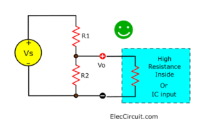
If connected to a device with high resistance, such as a voltmeter or input IC.
For more detailed information, please see the Impedance page. (coming soon)
Wasteful with power
The voltage dividers draw the current through the 2 resistors. Even no load at the Vo terminal. It will be like this because the current flows through both resistors.
It is a circuit that wasteful with power.
Read first for beginners: How do transistor circuits work
Transistor connection
If the output is connected directly to the base of the transistor, The Vo cannot be higher than 0.7V.
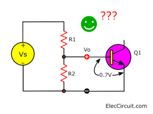
Because of the base-emitter of transistor connection, it behaves like a diode.
But we can use it well. When looking at examples of other transistor circuits. You will understand more.
Recommended: Learn Electronics with easy steps!
Learn: Designing small signal amplifier circuit using transistor simply
Voltage Divider 3 Resistors
Let’s say we add a resistor at the Vo terminal. Is it change Vo? Yes, the Vo change. But how many?
Let’s find out!
Look at the circuit diagram below.
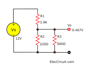
The Vo will drop and the current rises. Here is step by step to calculate.
- First, calculate the equivalent resistance of R2 and R3 in the parallel combine. Note: R1= 3.9K (3900 ohms) , R2=220 ohms, R3=560 ohms.
R = (R2xR3) / (R2+R2)
= (220×560) / (220+560)
= 157.948 ohms
Note: we will compare R = R2 in the formula for Vo (# 1). So, R2 is 157.948 ohms. I hope you understand my idea. - Find Vo = ?
Vo = (Vs x R2) / (R1+R2)
Note: Vs = 12V, R1 = 3.9K, R2 = 157.948 ohms.
Vo = (12 x 157.948) / (3900 + 157.948
= 1,895.376 / 4,057.948
= 0.467V
The key principle is to collapse any resistors to 2 resistors, according to formula # 1.
Using transducer inputs (sensors)
In normal, an input transducer (sensor) often changes itself resistance.
For an example of transducer inputs (Sensor) is LDR, Photodiodes, Phototransistors, Microphone, etc. I will explain them later.
We often use it in the voltage divider circuit. Then, when it changes. So, the output voltage changes, too.
Next, we can feed this signal voltage to other parts of the circuit. For example, the input of an IC or transistor.
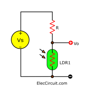
The sensor is one of the resistance in the voltage divider circuit. We can connect either top (R1) or bottom (R2). When we want the voltage (Vo) to be high. We can choose in 2 cases:
- Connect the sensor at the top (R1). The sensor has low resistance.
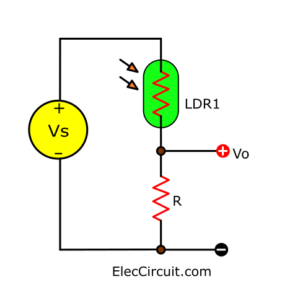
- Connect the sensor at the bottom (R1). The sensor has high resistance.
Choosing a resistor
The value of the resistor R will determine the range of the output voltage Vo. For best results. We need the voltage Vo that has a wide swing.
Note:
- Rmin is lowest resistance of the sensor.
- Rmax is highest resistance of the sensor.
And it will succeed. if R is greater than Rmin. But it should be less than Rmax.
We can use a multimeter to find the minimum and maximum resistance (Rmin and Rmax) of the sensor. The rough value doesn’t have to be very fine.
Then choose the resistor value: R = square root of (Rmin × Rmax)
or R = √(RminxRmax)
For example, you measure the LDR, Rmin is 100 ohms, and Rmax is 1M.
R = √(RminxRmax)
= √(100×1,000,000)
= 10K (10,000 ohms)
Credit: Voltage Divider Rule with Examples and Applications
Using a variable resistor
Often we use variable resistors (VR) instead of R which are constant. We can adjust Vo more easily.
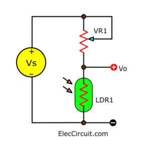
We can switch between the Variable resistor and the Sensor as our design.
For example, we can adjust the resistor. To set the brightness level more or less that will cause the changing conditions.
We should choose the potentiometer to be greater than the fixed resistor. And to be able to good adjusting. We should connect the series fixed resistor with a Variable resistor.
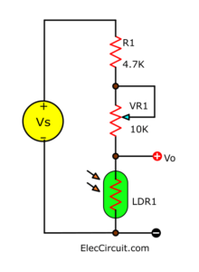
For example, if the suitable constant resistor value is 10K. We then replaced it with the R-4.7K series with the VR-10K. This allows the resistance to be adjusted from 4.7K to 14.7K.
How are you? I hope you understand the principles of the voltage divider better.
Download This Post as a PDF and all full-size of images
You may like these, too.
- What is capacitor? Principle working, types and how it works
- What is switching power supply vs linear, how does it work?
- Learn ON-OFF Light and Temperature Controller using 741 op-amp
GET UPDATE VIA EMAIL
I always try to make Electronics Learning Easy.
Related Posts


I love electronics. I have been learning about them through creating simple electronic circuits or small projects. And now I am also having my children do the same. Nevertheless, I hope you found the experiences we shared on this site useful and fulfilling.
thank you very much. this is very interesting and knowledgeable.
thanks a lot
Yes!!! This is an Important Topic!! Thank You so Much
i have absolutly no knowledge of electronics, you are the first source i found who explains it that even i can understand it. please keep doing what you do!
Hello Ben,
Thanks for your feedback. I am currently teaching my daughter to learn electronics. Hope these experiences will be useful for you too. If you want to learn more, don’t forget to tell us, Maybe I forgot about it we will learn it.