A DC motor controller has many forms. I am going to suggest you learn an h-bridge motor driver circuit.
So what? It is easy to do with a transistor or MOSFET drivers. And they are high performance, too.
I know you like to build a circuit project than tricky principles.
However, if you are a beginner. Learning H-Bridge motor works. It is definitely worth your time.
I try to draw a circuit diagram that looks easy to see.
Often we can see this H-Bridge motor driver on many controller circuits to moving of a robot.
Recommended: Learning electronics for beginners
How it works
We can design the circuit with MOSFET or transistor to control the rotating of a motor.
H-bridge switches
Which I suggest example them as switch, so easy to understand by see its working as Figure 1.
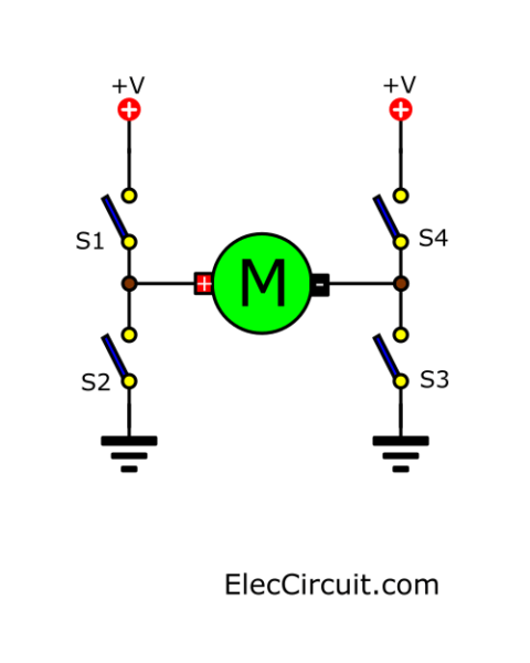
Figure 1: All the switches are OFF, causing the motor to not rotate.
In-circuit, we see that all switches are the open states. No the current flowing in the circuit, cause the DC motor can’t work.
Forwarding Mode
Then, look at Figure 2. When having the S1-switch (closed) and S3 (closed).
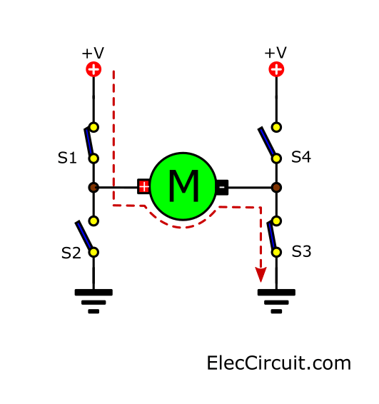
It causes the motor to get the current. As we notice that the current flowing into the positive terminal of the motor.
Making the DC motor rotated in features of forwarding form. Or Rotate clockwise.
Recommended: SCR circuit diagram
Reversed Mode
And, If both S4 and S2 are closed together. The Motor also get current that flows through them. But it will don’t the same first form. As Figure 3
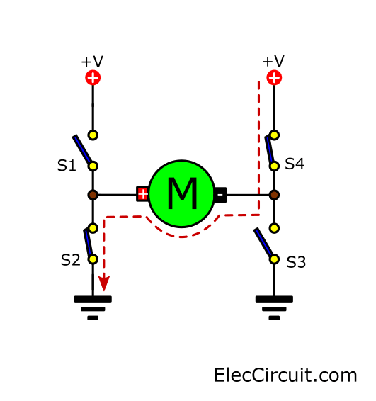
Because that current will flow through the negative of motor cause current reversed or Rotated back counter-clockwise direction.
Recommended: Learn transistor circuit works here
Start to apply transistors
We will try to use all the transistors as the switch. You see in Figure 4.
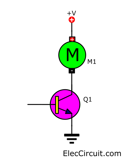
Figure 4 Using the transistor as switches.
When a base of transistors gets the current electricity. It causes the transistor running and the DC motor will rotate, too.
Read Also: Many about transistor driver circuits
Bridge transistor Motor driver
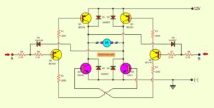
As Figure 5, we use the four transistors to connected into the H-bridge circuit.
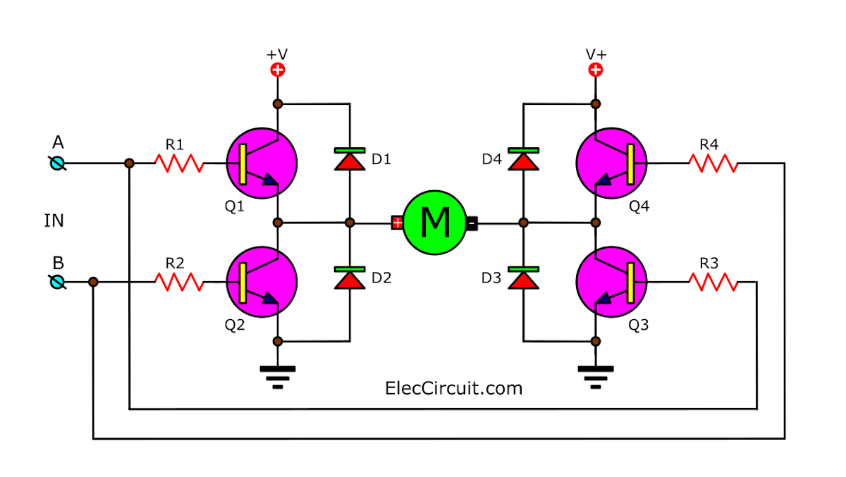
And add a diode to protect the electricity that may flow backward from the motor. Making damage to the transistor.
Check out these related articles, too:
- 12V-24V PWM Motor controller circuit using TL494-IRF1405
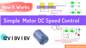
- Simple 12V | 9V | 6V Motor DC Speed Control with PWM mode
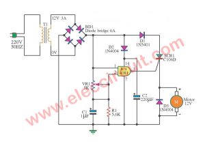
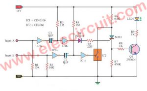
- SCR DC motor speed control circuit using IC-CMOS
Forward Rotate using transistors
In Figure 6 circuit, if we apply power to A-point. We will make Q1 and Q3-transistor works. Because they get IB-current into a base.
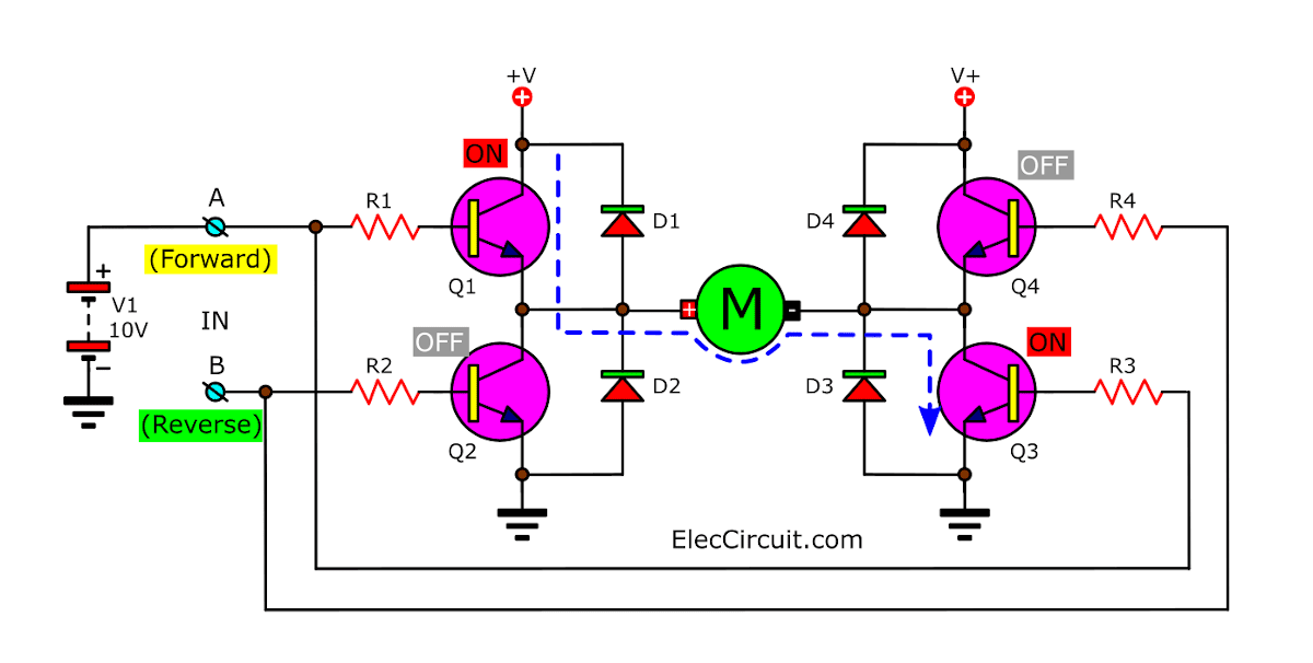
So, the motor will rotate on the forward direction. Because the electrical current flowing from Q1 into the positive of the motor. and flow through Q3 to ground successfully.
Recommended: 555 PWM LED dimmer circuit diagram
Reverse Rotate control using transistor
Then later as Figure 7, we change power supply-V1 point into B-point. The Q4 and Q2 also work by they get current from the base.
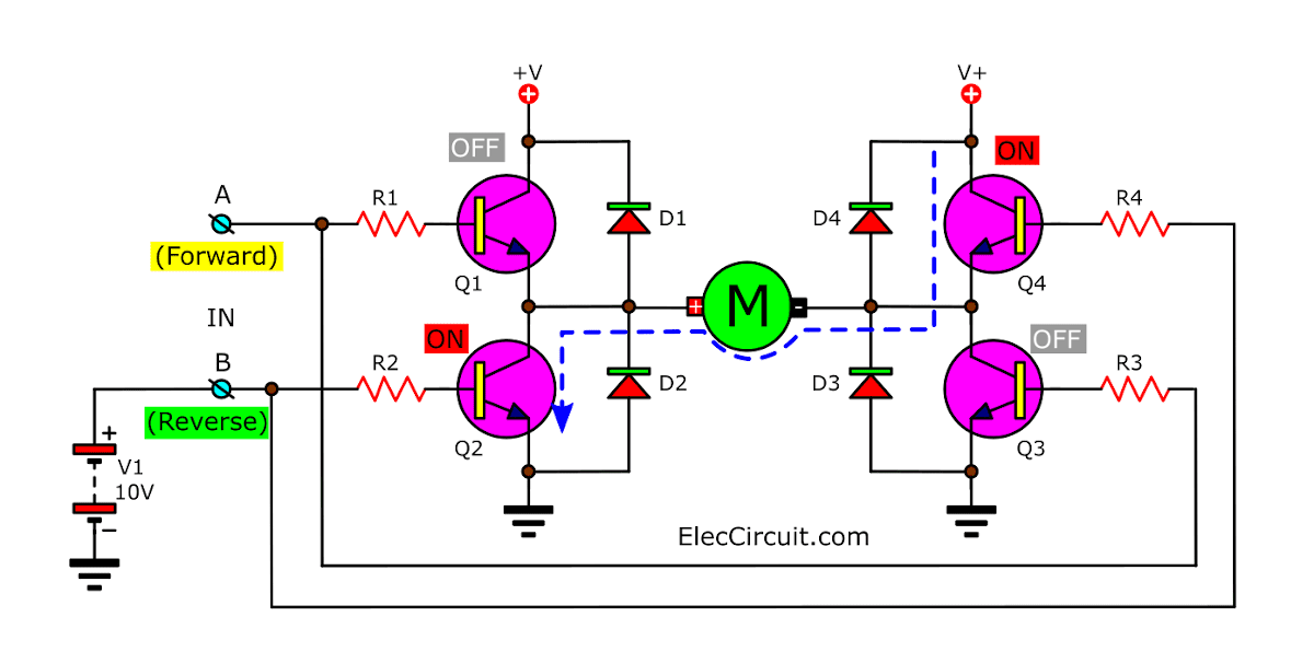
It makes them have the current flow through Q4 go to the negative of motor and through Q2-transistors to ground. Which flowing of current in this form causes the motor rotated in reverse direction.
More H-Bridge motor driver circuits
You can see the real application here The 2 channel DC motor driver on saving model

I love electronics. I have been learning about them through creating simple electronic circuits or small projects. And now I am also having my children do the same. Nevertheless, I hope you found the experiences we shared on this site useful and fulfilling.
hi friend, can you help me, how to make simple dc motor auto rotate (forward and reverse vice versa) ? I want dc motor move like a wiper (left to right vice versa) in low voltage (i want to use 18650 battery). i’m sorry for my English. thanks 🙂
Hi, my friend
Thanks for coming back to visit my site.
Your English is easy to read and understand, I use Google translate.
Please see: https://www.eleccircuit.com/the-2-channel-dc-motor-driver-circuit-on-a-saving-model/
It can control DC motor. What is the input signal, DC pulse?
Your question is interesting. But I regret that. I can’t explain it to be easy to understand. I’m good at drawing to make it easier to understand. Of course, it takes a long time, so if you can wait, that’s great.
Thanks 🙂
Apichet
How the GSM CONTROLLER works