A capacitor, or “cap” for short, is an electronic device that stores electrical energy in the form of electric charges on two conductive surfaces that are insulated from one another by a dielectric material.
A capacitor is a common and widely used electrical component that serves various functions and applications. You may have used it before, but let’s learn and better understand how a capacitor works, its types, and its basic application.
A capacitor also has the following basic electrical characteristics:
- Store and filter electrical currents.
- Block direct current (DC) from flowing through it.
- Allow alternating current (AC) to flow through it.
How Does a Capacitor Work?
As mentioned in the introduction, a capacitor is an electronic component that stores electrical energy and then releases that energy. A loose and simple analogy would be to compare it to a compressing spring with a ball on top.
(1) When left alone, a spring stays in the resting position or equilibrium, as does a capacitor. (2) But when we exert energy on a spring by pushing it down, it stores that energy as potential energy. Similarly, applying electrical energy to a capacitor stores the electric charges as potential energy.
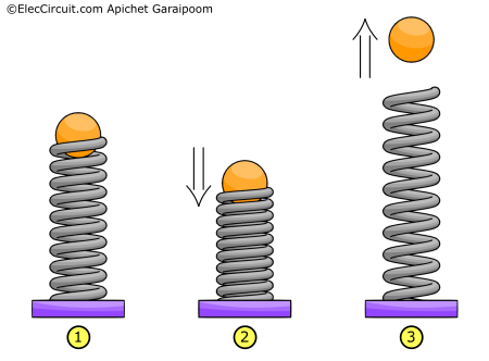
(3) However, when we release the pressure on a spring, it expands with the force of the potential energy, launching the ball upward. Comparably, a capacitor can also release its electric charges. This process is known as discharging, which we will discuss later.
Basic Structure of a Capacitor
Now that we know the basic idea of how a capacitor works, let’s see the physical composition and how it affects the usage and specifications of a capacitor.
In its most basic form, a capacitor consists of two ‘plates’ with wiring leads separated by a ‘dielectric.’ Plates are made of metallic conductive materials like foil, metal beads, or electrolytes, while a dielectric is a nonconductive insulation such as glass, mica, paper, ceramics, or even air.
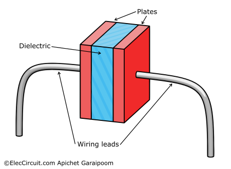
Generally, we may refer to a type of capacitor based on the material composition of its dielectric. For example, a capacitor with a ceramic dielectric is called a “ceramic capacitor.”
Specifications of a Capacitor
The value of a capacitor is referred to as its capacitance, or simply its ability to store electrons. It is the value that is listed when buying a capacitor, alongside the rated voltage.
A capacitance C is measured in units of farads, with the abbreviation of F, defined as the ratio of coulombs of charges on each plate and the voltage between them (C = charge ÷ voltage). To put that into perspective, a 1-farad capacitor supplied with 1V stores 1 coulomb of charges or about 6.241 × 10¹⁸ electrons.
However, in practice, a farad is a very high-value unit, and most capacitors we commonly use have much lower values than that, with the majority having the following two prefixes:
- μF as microfarads (millionths of a farad) for large capacitors.
- pF as picofarads (trillionths of a farad) for smaller capacitors.
So to visualize:
1- Farad = 1F
1-Microfarad = 1μF = 0.000 001F = 1/1,000,000F
1-Picofarad = 1pF = 0.000 000 000 001F = 1/1,000,000,000,000F
as well as
1-Picofarad = 0.000 001μF = 1/1,000,000 μF
Or here is the equivalent table between the three units.
| Farad (F) | Microfarad (μF) | Picofarad (pF) |
| 0.001 | 1,000 μF | 1,000,000,000 pF |
| 0.0001 | 100 μF | 100,000,000 pF |
| 0.00001 | 10 μF | 10,000,000 pF |
| 0.000001 | 1 μF | 1,000,000 pF |
| 0.0000001 | 0.1 μF | 100,000 pF |
| 0.00000001 | 0.01 μF | 10,000 pF |
| 0.000000001 | 0.001 μF | 1,000 pF |
Factors Affecting Capacitance
If you recall, the basic structure of a capacitor is two plates close together with a dielectric between them. We can define an overlapping area of the two plates as A, a gap between the plates as d, and the permittivity (polarizability) of a dielectric as ε.
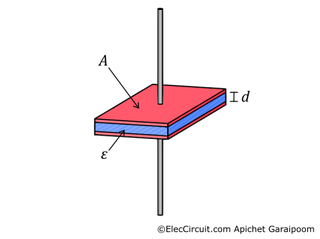
In this simple model, let’s assume that the electric field is only directed between the plates and that the electric charge is spread evenly on them. However, in saying that, this model still applies to most capacitors.
Since we already know that capacitance is C = charge ÷ voltage, we can substitute charge for an area of the plates, A, times the dielectric’s permittivity, ε, and the voltage across the plates for a gap between the plates, d. This resulted in the following equation:
Therefore, the three factors that affect the capacitance of parallel plate capacitors are:
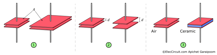
- The total overlapping area between the two plates—the bigger it is, the greater the capacitance.
- The distance between the two plates—the farther they are from each other, the lesser the capacitance.
- The permittivity of a dielectric material—the higher the permittivity of a dielectric, the higher the capacitance.
Capacitor Working Principle
We already know the basics of how a capacitor works, in that it stores energy. So let’s better understand how it charges and discharges electrical energy.
Charging Capacitor
First, let’s set up a simple circuit to help us understand the operation. It consists of a capacitor connected across a battery and a switch that controls the current flow.
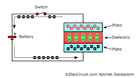
When we apply voltage to a capacitor by turning on the switch, an electric field forms between the two plates. This causes negative charges to gather at one plate and positive charges to gather at the opposite plate.
Like magnets, these charges on each plate repel the same polarity charges on the opposite plate, resulting in both plates having equal and opposite charges.
As a dielectric subject to an electric field that develops between two plates, it gets polarized, reducing that electric field and increasing the plates’ capacity to hold charges. This allows each plate to store more charges, resulting in greater capacitance.
Also, note that charges did not actually flow through the capacitor itself because of the dielectric that functions as an insulator, but they could still flow through the power source.
Discharging Capacitor
Now that the capacitor has been fully charged, charges will remain on each of the plates for some time before slowly leaking through the dielectric and completing the charges. However, we can speed up that process by connecting both plates together.
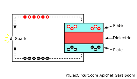
When the circuit is completed, positive and negative charges are immediately drawn to each other before completing the charge and releasing a burst of energy. This event is referred to as discharging.
Learn: Relationship Between Current and Voltage
Type of Capacitors
Capacitors can be summed up into two major types, the first being a fixed value capacitor followed by variable capacitors.
Fixed Capacitors
The fixed capacitor is the most common of the two. It is labeled according to its dielectric, such as ceramic, mica, mylar, polystyrene, polyester, paper, electrolytic, tantalum, etc.
But we often use electrolytic, ceramic, and mylar because they are well suited for general use and inexpensive.
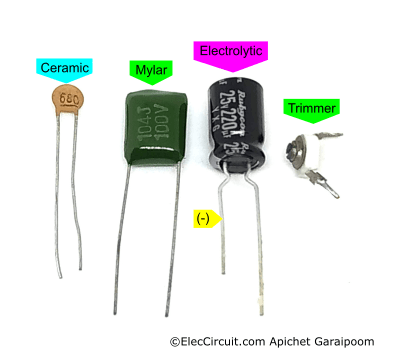
We will only be covering two types, electrolytic and ceramic, since they are the most used ones out there.
Ceramic Capacitors
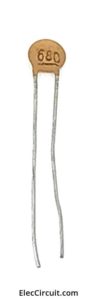
Appearance-wise, it is round and flat, orange in color, and has two symmetrical wire leads, as shown below. It is a non-polar type of capacitor, meaning it does not have polarity.
Generally, it can withstand a voltage of around 50V to 100V and has a capacitance ranging from 1pF to 1μF. There are also many classes of ceramic capacitors for different applications; however, you can just pick one whose capacitance matches what your circuit calls for.
Electrolytic Capacitors
Unlike ceramic capacitors, electrolytic capacitors do have a polarity that needs to be taken into account when working with them. If a voltage of the wrong polarity is applied, the capacitor will get damaged immediately.
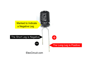
To prevent that from happening, a marking for the negative lead is made visible on the side of the capacitor, plus a brand new one should also have asymmetrical wire leads, with the shorter one being negative (cathode) and the longer one being positive (anode).
Electrolytic capacitors often have a tall cylindrical shape, although smaller rectangular SMD styles are available. They are often used in a power supply circuit as a filter or to store heaps of energy.
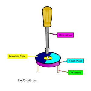
Variable Capacitors
Variable capacitors typically operate by having a nonmoving plate and a moving plate; the capacitance is controlled by rotating a rod affixed to a moving plate. Rotating a rod one way increases the overlapping surface area of the two plates, thus increasing the capacitance. Rotating oppositely decreases the area and lowers the capacitance.
They can generally be divided into two types: trimmer and rotary variable capacitor.
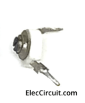
Trimmer Capacitors
A trimmer, apart from being used as a variable resistor or potentiometer, is also available in a capacitor form. It is designed to be tuned once or twice during or after the circuit’s building process, resulting in it having very low adjustment cycles over its life.
A trimmer capacitor comprises two semicircular plates stacked on top of one another within a plastic shell, with an indent on top that allows you to rotate the position of the moving plate with a flathead screw bit.
It is often used in an oscillator circuit, for example, in an FM wireless transmitter or a digital watch.
Rotary Variable Capacitors
A rotary variable capacitor uses a mechanic similar to that of a trimmer capacitor but is more robust and permanent. It is usually made up of multiple half-circle plates, either stationary or affixed to a rotating axial shaft in the middle.
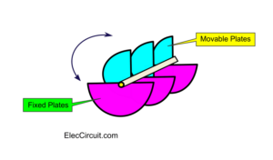
A very fine control over the axial rotation, and to an extent capacitance, can be achieved easily with a reduction gearing. Furthermore, on a single axle, there could be more than one set of half-circle plates, meaning that you can tune more than one device at a time.
We often use this type of variable capacitor to tune radio receivers or transmitters.
How to Read Capacitor Code
Since most ceramic and mylar capacitors are small, manufacturers tend to label their capacitances with shortcodes. Here is what each digit of the code means:
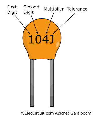
- The first and second digits are fixed numbers with a unit of pF.
- The third digit is the multiplier, in ten raised to the number (10n); for example, 103.
- The fourth digit is the tolerance level, such as J = 5%, K = 10%, and M = 20%.
Here are a couple of examples:
- What is the value of a 101K capacitor?
First digit = 1
Second digit = 0
Multiplier = 101, or ends in 0pF
Tolerance = K = 10%
101K = 100pF = 0.0001μF with 10% tolerance. - What is the value of a 473K capacitor?
First Digit = 4
Second Digit = 7
Multiplier = 103, or ends in 000pF
Tolerance = K = 10%
473K = 47,000pF = 0.047μF with 10% tolerance. - 102M : 10 x 102 pF = 10 00pF, which is 0.001μF with 20% tolerance.
- 103J : 10 x 103 pF = 10 000pF, which is 0.01μF with 5% tolerance.
- 104J : 10 x 104 pF = 10 0000pF, which is 0.1μF with 5% tolerance.
Cautions When Working With Capacitors
Firstly, every capacitor has a voltage rating, or what we call the working voltage (WV), which tells us the maximum voltage that the capacitor can handle.
Supplying voltage exceeding the working voltage of a capacitor will cause a dielectric breakdown, which is when a strong electric field causes the dielectric material to become conductive. This creates a short circuit between the two plates, which usually damages or even kills the capacitor.
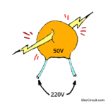
To prevent this from happening, you must check the voltage rating carefully every time you pick a capacitor for your circuit. In general use, we usually reserve the working voltage of a capacitor to be twice that of an actual operating voltage.
For example, in a 25V or less circuit, we would choose a capacitor with a voltage rating of 50V.
High Voltage Retained Within a Capacitor
Capacitors can hold their charges long after the power is disconnected, even after removing them from a PCB. Considering that a large electrolytic capacitor usually holds up to 100V or 200V. So if something like a metal wire touches both leads, it will cause a short circuit, releasing an extreme amount of energy that can even melt metal.
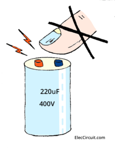
This means that if you were to, say, accidentally touch both leads, the result would not be just a small shock but a severe electrical burn or even death.
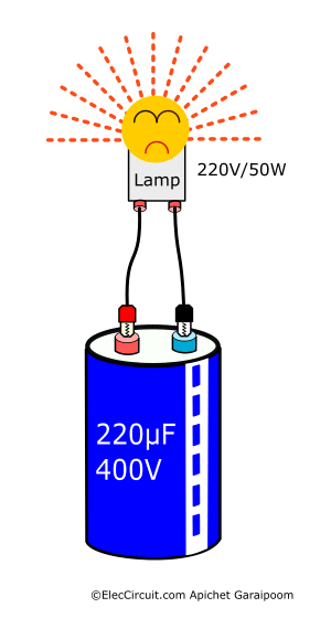
That is why high-voltage capacitors need to be handled with care; they are usually stored separately from one another and have their leads cut short. Another simple method is to connect capacitors to a load, like a Light bulb (220V/110V), to discharge the voltage after you are done with them.
Capacitor Applications
A capacitor is an essential electronics component that is used in numerous circuits. Here are some of the most popular applications and the reasons for using them:
Power Supply Filter
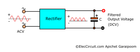
We always use filter capacitors in a power supply. They help smooth the pulsating voltage into a steady direct current (DC). If you are interested, you can read more about it here.
Digital Spike Remover
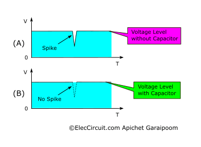
For a digital circuit, voltage supply stability is paramount, and any spike will cause the circuit to become unstable or run an error. Adding one capacitor across the power supply will help reduce any transient voltage spike, increasing the circuit stability.
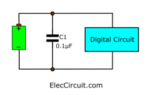
When there is a sudden drop in voltage, the capacitor discharges and helps supplement the missing voltage, resulting in smooth voltage with a minimum impact on the load.
Capacitor Switch Transient Protection
When you turn a switch on and off inside your home, there is a chance that some unwanted behavior will occur, such as flickering light bulbs or audible noises from certain electronics.
This might be because when a switch pad made contact, it caused a sudden surge of current and thus a spike in voltage. Even for a short period, these spike voltages can affect electronics in the same house circuit.
But as you know, a capacitor can help reduce this spike voltage. By connecting a capacitor across the switch, it will act as a load and absorb the spike voltage before it reaches the rest of the circuit.
Conclusion
A capacitor is a particularly interesting electronic component, from its different operating principles depending on the current type to its many forms and usages. Getting to understand all of its characteristics can be challenging. But we hope that you at least pick up something useful about capacitors in this article. If you have any other components you would like us to cover, be sure to let us know. Thank you for reading.
Download This Post as a PDF and all full size of images
Here are a few related posts you may find helpful:
- Uses of capacitors | RC circuit time constant and Coupling
- Add capacitance meter range for general digital multimeter
- Electronic Circuit symbols

I love electronics. I have been learning about them through creating simple electronic circuits or small projects. And now I am also having my children do the same. Nevertheless, I hope you found the experiences we shared on this site useful and fulfilling.
Bom dia !
Grato .
Preciso de circuito DIY para audio 2.1 com Bluetooth e TWS .
Novo ou usado .
Exs.
ZK-TB22 , e
ZK-LT23 .
Se houver custo , desde já
concordo .
Grato .