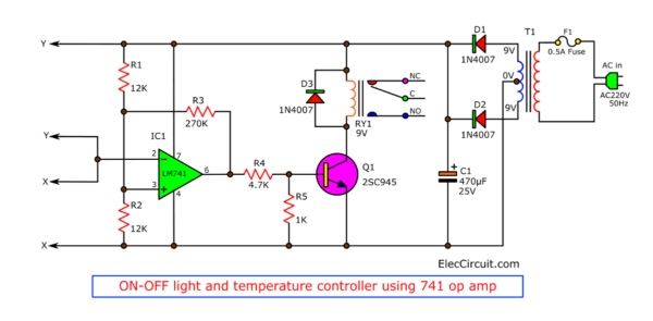
I like to learn about the circuits used to detect temperature and light. To control various loads. Are you the same as me? Here is an On-Off Light or Temperature Controller Circuit using a 741 OP-AMP Comparator.
Some people say that learning simple circuits is a waste of time. Because in this era, almost everything is already well-made and ready to use. We don’t even need to design the circuit ourselves; we just need to assemble pieces into a project well enough.
But friends, do you ever think the same way as I do? That we should use various things thoroughly; both old and underrated devices are still valuable and worth using. In addition, learning these things is a challenging activity and will definitely be a good foundation in electronics learning.
The Circuit Concept
Imagine a hot day; you would be more comfortable with a ventilation fan. But when the weather is cold, we should turn off the fans because they are not helpful.
Related: 2 ideas of Car overheat alarm circuit
This circuit will make our lives easier. Because it will turn the fan on or off automatically depending on the temperature. So we do not have to waste our time doing it ourselves.
I am worried that you will not understand. Let’s look at the block diagram below; maybe it will help you understand its process.
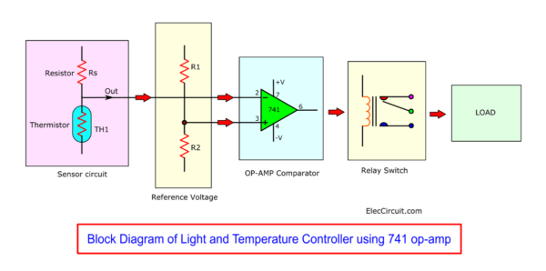
This circuit uses a thermistor as a temperature detection device or an LDR as a light detection device.
Like the previous circuit, we used a relay switch to control the electricity for the electrical appliances (load).
But the interesting part is the OP-AMP Comparator. Because it is the core of this circuit and more complicated than others.
OP-AMP Comparator
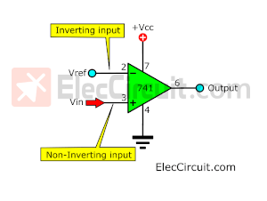
This project uses a 741 OP-AMP in comparator form, with a reference voltage level for comparison. An OP-AMP voltage comparator is both easy and convenient.
Since one of the OP-AMP’s important characteristics is that the open-loop gain is very high (100,000 times) without any feedback signals.
Thermal or optical sensing devices will be arranged in the form of a voltage divider circuit. To compare with the reference voltage level from above.
The output voltage of the 741 OP-AMP will be used to drive other circuits such as the counter circuit, relay controller circuit, timer circuit, etc.
Recommended: Diode Temperature Sensor Switch using 741
There are mainly two types of OP-AMP comparators, consisting of an inverting and a non-inverting one.
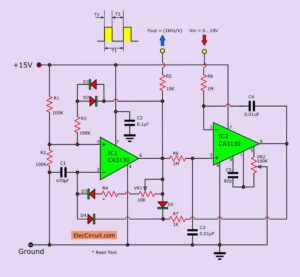
Inverting op-amp comparator
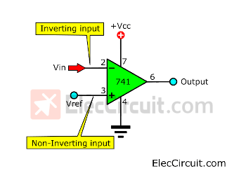
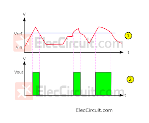
When we enter an input voltage (Vin) into the inverting input (Pin2) and set the non-inverting input (Pin3) to receive the reference voltage (Vref). It will then compare the variable input voltage with the constant positive reference voltage, as shown in graph (1).
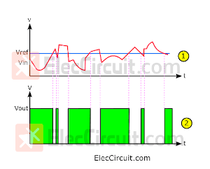
But the output can only have two states—High and Low—according to the results of the comparison of Vin and Vref, as shown in graph (2).
If Vin is lower than Vref, the output will be Low.
In contrast, if Vin is higher than Vref, the output will be High.
Are you a beginner? Learn Basic Electronics
Non-inverting op-amp comparator
In contrast, Connect Vref to inverting input. And use non-inverting as the input.
See the image below.

The output voltage will be VCC. If the waveform of the input is high as well.
The output has only 2 voltage levels, VCC and 0V. So, we can easily control it via the relay. In addition, it has logic-like conditions in digital circuits. May be applied as a count circuit or display other results
Also: Simple temperature to voltage converter circuit
Do you understand?
How this circuit works
I want to help you understand better. Almost every time I wonder. I often learn from real circuits.
Look at the circuit. See many devices. Don’t be confused.
Here is a step by step process.
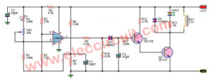
IC1 is a voltage comparison circuit, in an inverterting mode. Include many resistors. But it is easy.
With R1 and R2 determine the reference voltage(Vref) at pin 3. They are a voltage divider circuit. When both R1 and R2 are equal, the voltage at this point. It is half the power supply.
The XY connection point consists of a voltage detection circuit at pin 2. If this working. Then, the comparator circuit run, too. It makes the output is VCC.
The current flows through R4 and R5. And, has voltage across R5. It causes transistor Q1-2SC945 works. And the relay works, too.
The Diode-D3 absorbs this current spike of a relay coil. To protects the external relay driver circuit.
Recommended: Making Simple Light-activated relay circuit with PCB
For the detection circuit on the input at pin 2. We can choose 4 types, see in the picture below.
Note: This image is old. But with a similar circuit structure. We can see that you can use it with a 9V or 12V power supply. And can be used with transistor BC549 or 2SC945 (but the shape is different)
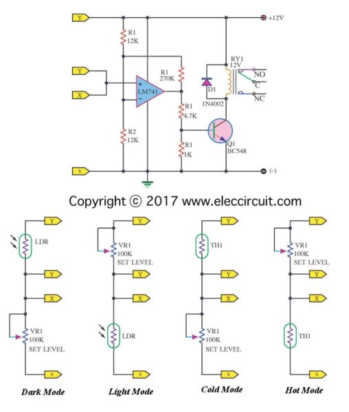
- Dark Mode:
The relay will work when it is dark. Because the LDR is higher resistance. So, the voltage across it is low. - Light Mode:
In contrast, the relay will work when it is light. Because the LDR is lower resistance. So, the voltage at pin 2 is low. The IC1 compares input voltage and Vref. It makes the high voltage at output to drive relay runs, too. - Cold mode:
It is similar to LDR working. The relay will work when the thermistor gets a low temperature. The TH1 is a higher resistance. Then, there is a low voltage at pin 2. So, the output is a high voltage. - Hot Mode:
Imagine you use this mode to control the fan. The relay will work when the thermistor gets a high temperature. We switch position TH1 and VR1. It will work in contrast.
Also, we can adjust VR1 to set sensitive of detecting in every mode.
Read Also: Automatic led night light switch
The power supply:
We use 9V to 12V DC power supply. See the circuit. They include T1, D1, D2, and C1 are 9V DC unregulated power supply.
See other simple electronic circuits
Parts you will need
0.25W Resistors, tolerance: 5%
- R1, R2: 12K
- R3: 270K
- R4: 4.7K
- R5: 1K
- VR1: 10K Potentiometer Trimmer
- C1: 470uF 25V Electrolytic capacitor
- IC1: LM741 op-amp IC
- Q1: 2SC945, 45V 300mA NPN transistor
- D1,D2,D3: 1N4007, 1000V 1A Diodes
- RY1: Relay with SPDT 10A min switch. Coil Voltage 12V. Coil resistance 150-600 Ohms
- PCB, and others
Learn: How do SCR works and basic circuits
How to build it
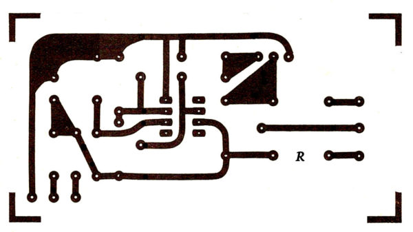
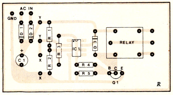
This project is easy. So, you may assemble it on an universal PCB. Or some want to make the PCB you can see the PCB layout and Component layout below.
I trust you are good in electronics you know how to build electronic in simple ways.
Here are a few related posts you might want to read:
- How to make automatic daylight sensor switch Project
- Automatic night light circuit using SCR
- 10 sec to 30 min Time Delay circuit with relay transistor

I love electronics. I have been learning about them through creating simple electronic circuits or small projects. And now I am also having my children do the same. Nevertheless, I hope you found the experiences we shared on this site useful and fulfilling.