This is a 1.5V battery tester circuit using LM324. It can measure the voltage of the 1.5V battery, AA or AAA. In a decimal point. How? Easy to use by reading LEDs display,
Accurate because the IC-LM324 is a voltage checker. Measure all battery of any kind, whether plain battery or rechargeable battery(1.2V).
Want to know about LM324? Learn HERE
How does it work
The principle of the circuit as shown in block diagram Figure 1. When we bring the battery that requires test the voltage in this circuit. The circuit will get voltage to compare with voltage internal the circuit.
Which come from the battery 9 volts, then display with LED, If the battery still has a lot of power. The LED will glow as the voltage of a battery that testing.
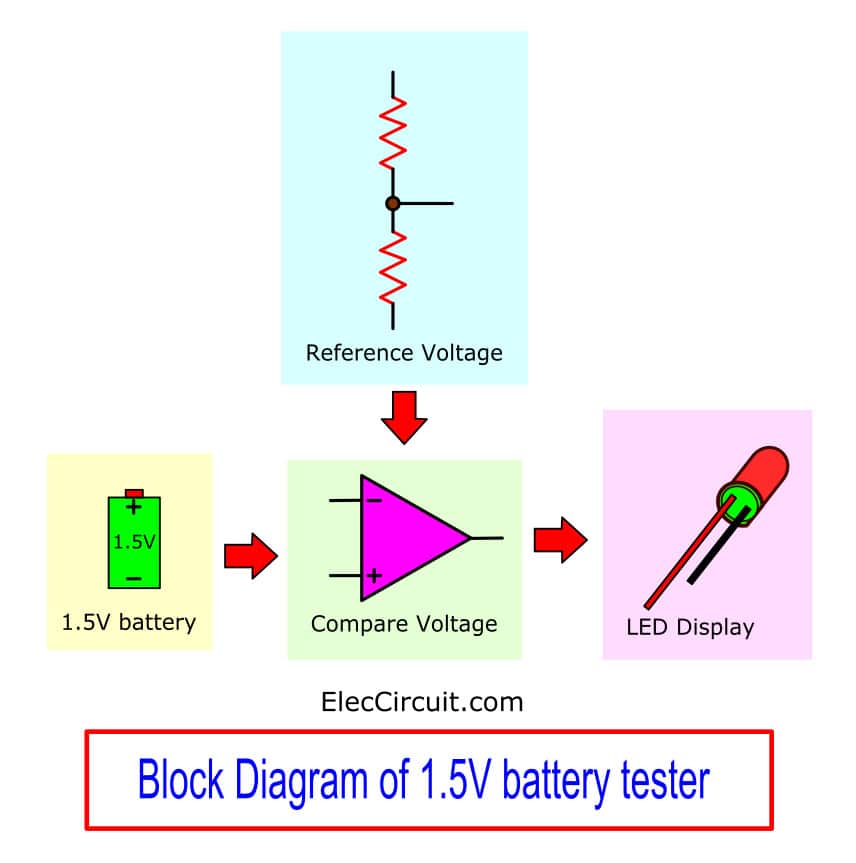
The block diagram of the 1.5-volt battery tester circuit
We see the main principle successfully. Then, we see each component as in Figure 2. The begin with, diode – D1 act as a protector when we connect the battery that the Wrong terminal. The capacitor-C1 and C2 serve to increase to stable to the circuit.
The resistor-R1, LED1, the potentiometer-VR1 and R4 to R11 serves to feed the reference voltage to IC1 and IC2. To compare with a voltage of the battery that is tested at pin 12,3,5 and 10 with the reference voltage at pin 13,2,6 and 9 of both ICs. Which combined with all eight series.
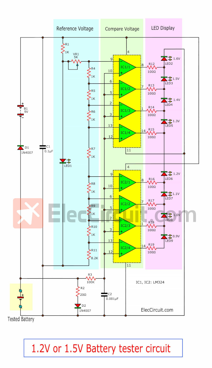
The circuit of the 1.5-volt battery tester using LM324
Then to display with LED2 to LED9 by has R12 to R19 are limit current to all 8 LEDs display.
The IC2/4 is voltage meter (the compare voltage circuit) that have lowest about 0.9 volts. If the voltage of the battery has a level lower than 0.9 volts, just a little also will cause the LED9 glow.
The check section of the remaining seven series also is set the voltage out already. The battery that gets to check has voltage at which LED that will be lightness. The diode-D2 and resistor-R2 serve as a load of the battery is tested.
By normal battery(good) that we use will have a voltage about 1.6 to 1.4 volts. Unless The battery can be recharged will have voltage about 1.2 volts. If lower this will must recharge now.
The testing and adjustable
The test is very simple, just put 9 volts Battery for use as a reference voltage and a small size battery 1.5V AA To put in place a fully tested. The LED displays the voltage of the battery.
But if LED does not display to sorry, You assemble the circuit. But do not panic.
You can verify the authenticity as Figure 3. Check the soldering, wiring because of the slight. We overlooked. Cause the circuit does not work.
After modifying until finished, Then the tune. By using a new 1.5V battery put to the test. Then adjust VR1 until LED3 display at 1.5V glow I just finished customizing. And ready to use.
The component list
IC1,IC2: LM324, Quad/ 1MHz/ Operational Amplifiers for Commercial/ Industrial/ and Military Applications
D1,D2: 1N4007, 1000V 1A Diodes
C1: 0.1uF 50V, Ceramic Capacitor
C2: 0.001uF 50V, Ceramic Capacitor
Resistors 0.25W 5%
R1,R4 to R10: 1K
R2: 20 ohms
R3: 100K
R11: 8.2K
R12 to R19: 100 ohms
LED1 to LED9: LED as you like
VR1: 5K potentiometer
Socket IC DIP14
Battery holder AA size
Related Posts

I love electronics. I have been learning about them through creating simple electronic circuits or small projects. And now I am also having my children do the same. Nevertheless, I hope you found the experiences we shared on this site useful and fulfilling.
Does this circuit really work!??