Why your circuit does not work? Because the battery is run out.
These low voltage indicator circuits may helpful for you.
If you can know before and change a new one right now.
It makes you not have to waste time when using those projects.
Is it great? if you have a lot of ways to do it.
I am going to show 8 circuits ideas.
Below: You will see using basic components like transistors, SCRs, Zener diodes, And IC circuits. Which sometimes suitable for you in a different case.
Even more importantly they are a so good teacher to improve your electronics skills.
Ready to get started?
# 1: Simple Battery Low Voltage Alarm Indicator
The first circuit is the simplest battery indicator circuit. It can apply to an input voltage of 3V to 15V. The LED will begin to light up. we can adjust VR1 to set a level of checking voltage.
When the battery voltage reduces down to a set point. The LED will bright immediately.
Look: in the circuit.
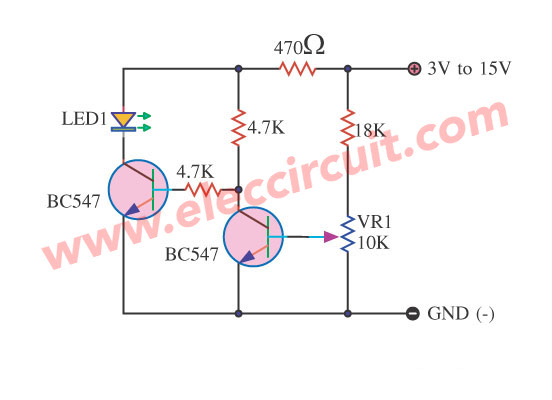
They use a few electronics parts also just transistor BC547 and others.
In normal it uses current about 3mA. But when LED glows. the circuit use current more to 15mA.
Do you know how it works?
It is easy.
Imagine you use this circuit to a 6V battery. A current flows through 18K and VR1 to the base of Q1. The Q1 runs, because getting a current bias. But Q2 does not run. The LED goes out.
In contrast, the battery is lower voltage down. Then, Q1 works down. But the current can flow to the bias base of Q2. It causes Q2 runs, LED1 glow up.
You can try to change any resistors as the input voltage.
So what? See the next better circuit.
Recommended: Recycle Free Li-ion battery from E-waste
#2: Low voltage Ni-MH battery indicator
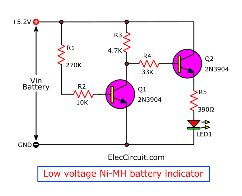
We use this circuit for indicating a voltage level of Ni-HM or Ni-cad battery. If it is lower than 4.8V. An LED in this circuit will glow up. Or it indicated that the battery is running out.
Look at the circuit.
Let me explain to you how it works.
When this circuit measures the voltage level of the full Ni-HM battery.
A current flows through R1 and R2 to bias a base of Q1.
It causes Q1 runs. But makes a Q2 transistor does not work.
Because no current to base of Q2. Makes LED1 go out.
But in contrast, the battery voltage is lower than 4.8V. The transistor Q1 will stop conducting the current. And transistor Q2 will run instead.
So, LED1 show up to alert us the battery nearly run out.
# 3: LED battery status indicator circuit using 4 Transistors
We connect this circuit to indicate the status of the battery. It is full or less energy. It is special to both circuits above. In normal LED light up. But low battery LED will blink. Is it nice? We can notice it easily.
Look at the circuit below.
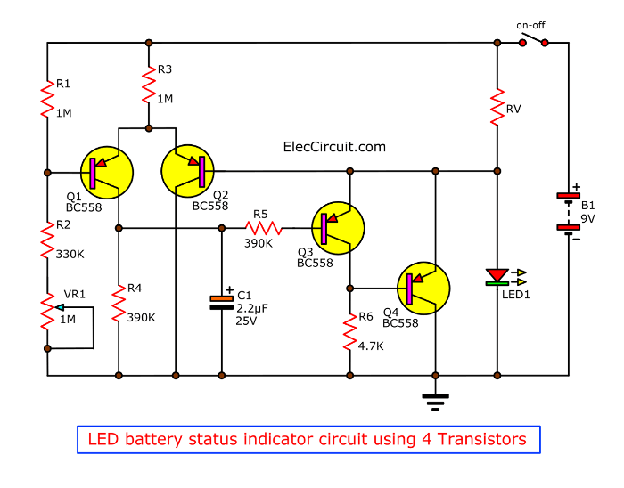
First, see you see 4 transistors and components more than 2 circuits above. Do not worry. It is also easy.
Here is a step-by-step working:
An LED1 is power on and LED display status. And important it makes a reference voltage, too. The voltage of LED1 is stable at about 2V.
Ths voltage flows to a differential amplifier circuit. Which includes T1 and T2 are a main.
Suppose that the input voltage from the battery is low.
It causes the voltage at the base of Q1 is lower than the voltage of LED1. So, Q1 runs.
Then a current flows to Q1 to charge C1 slowly. It makes Q3 is OFF, and Q4 is ON. So, the LED goes out.
Next, Q2 gets a bias current. The Q2 turns On. The voltage at the base of Q2 is lower than the base of Q1.
It makes Q1 is OFF again. While C1 discharge through R4. This makes Q3 is ON and Q4 is OFF. So, LED1 glows again.
This will continue alternately like this. We will see the flashing LED according to this status.
We can set the voltage by adjusting VR1. And C1 define a frequency of LED blink.
The RV is a limiting current resistor of LED1. You may try to use any value. According to the size of the LED and the battery voltage level.
For example, 1K for 9V battery. If you try then you will get any results. Don’t forget to share it with me. Thank you.
# 4: LED Display Low 9V Battery using SCR
3 the circuit above we use the only transistor. Do you like them?
Sure, we should learn in many ways.
In this circuit, we will use SCR. Yes, SCR! to do like a transistor. But may better…Why? Read now. You may like it too.
Look:
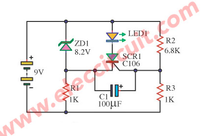
An LED1 will glow up when a level voltage of 9V battery is lower than 8.3V. Sure this idea for 9V battery. But you can apply to any batteries easily. If you read to the end.
Here is a step-by-step process.
Suppose that we use a new battery. It has a full voltage of about 9V.
Then a current flows through R1 to ZD1.
Which uses a Zener diode is a reference voltage. Parts Number: BZY85C8V2 400mW for 8.2V 400mW.
The voltage at ZD1 is 8.2V. And the voltage of R1 is 9V-8.2V = 0.8V.
Then, see SCR in the circuit. The SCR works are similar to a transistor. It drives LED is ON-OFF. By controlling of gate current. And it will turn on when the gate and cathode are higher than 0.7V.
Look:
Some current flows through both resistors R2 and R3 are a voltage divider circuit. It appears voltage across R3 is about 1.1V compare with the ground.
But when we compare with the gate of SCR1. It has a difference that 0.3V only. So, SCR does not run.
Do you follow me? Hope you understand.
In contrast, the input voltage of a battery is lower than 8.4V. The voltage of R1 is 0.2V only. And Voltage at R3 is about 1.04V.
Now, the gate gets a trigger voltage of 0.7V. It runs immediately. The LED1 glows.
We recognize the battery is low voltage. It needs to change a new one.
Are you wondering why the C1 across is between the gate and cathode leg of SCR?
The first time we connect the circuit to the battery. It has a spike voltage too much. May make SCR1 run fast. It is necessary to turn off SCR first.
Because of the discharge of a capacitor, the voltage G-K is zero in first.
Do you understand?
# 5: Low Volt Battery LED Display using LM3909
For this circuit, I am going to show just only little ideas. you may not do it. Because you cannot buy LM3909 in normal stores.
But we want to learn many circuits. Some may have them in his stores. Yes, you can try it is easy!
Look at the circuit.
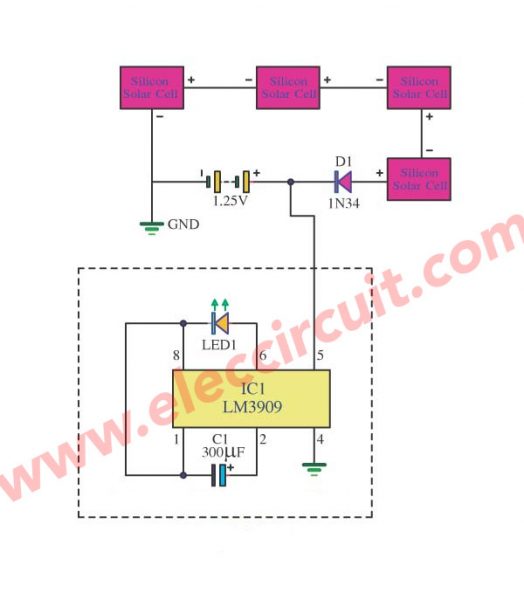
If you charge a one 1.2V Ni-HM battery 500mAh by a solar cell charger. This is easest with a single diode for battery Charger automatically is at day time.
This circuit use LM3909 and only one capacitor as an LED flasher. To display when solar cell charging.
#6: Low Battery Voltage Indicator using IC-8211
This is another one of the low battery Voltage Indicator circuits. The model is easy. It can show the level voltage, the minimum of the battery with an LED display.
Look at the circuit.
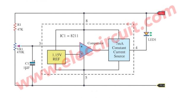
It uses IC8211 or ICL 8211 (Programmable Voltage Detectors) as main parts.
When the voltage of power supply is lower to at a defined point. But do not lower than 1.15V.
A voltage comparator circuit within 8211. It recognizes this voltage level. So it gives a current comes out of pin 4. And LED1 glow up.
This circuit uses current altogether about 7mA only. And can set a minimum voltage with VR1. Besides, it can work well just 4 small parts only. See more detail in the circuit.
# 7: Simple voltage indicator using OP-AMP 741
The previous circuit used IC which May be difficult to find and expensive. In fact, we can use a popular type of IC is OP-AMP. It has a good feature to check a level voltage.
To does not waste time. See the circuit below.
It is the easiest voltage indicator circuit using OP-AMP 741.
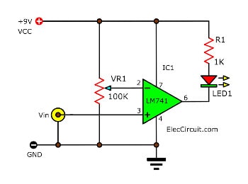
Suppose that we adjust VR1 until the voltage at pin 2 is 3V.
Then we enter input voltage is 3.6V. It makes pin 6 of IC1 741 op-amp is high voltage approx 9V. But LED1 goes out. Because of reverse bias.
In contrast, we reduce the input voltage down to 2.5V. The output of IC1 is low voltage about 2V. But LED1 glows up. Because it is forward bias.
Here is a simple circuit. What is more? Read the other one.
8# Low Volt Alarm using Comparator
In this circuit, we use LM339 Quad Comparator. It is one type of op-amp that uses for check level voltage specifically.
Look at the circuit.
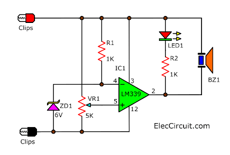
When we apply this circuit to a battery. Then, the battery runs out of power or low voltage. A LED and Buzzer emit a loud sound.
It looks like previous circuits. But it is a difference, more accurate and easier to adjust
We add R1 and ZD1 to create a reference voltage (6V) to pin 4 of IC1.
At pin 5 connect to VR1 to set input voltage.
Imagine we set at 6V. When input voltage lower than 6V. LED1 glows and BZ1 sounds up.
Conclusion
There are a lot of Low Battery Voltage Alarm indicator circuits. Each circuit has advantages and disadvantages, but different. We can choose according to the suitability of each project. Which one do you want to do?
Related Posts

I love electronics. I have been learning about them through creating simple electronic circuits or small projects. And now I am also having my children do the same. Nevertheless, I hope you found the experiences we shared on this site useful and fulfilling.


Please set project circuits
vmak
Dear Sir
Plz Send to me Cricuit Dia gram Of 48v Dc when the volt 46,0v cut off relay off,,,, tabx
Dear Sir
Plz Send to me Cricuit Diagram Of 48v Dc when the volt 47.5 volt cut off relay (N/O) will operate as NC.
as well as this 47.5 voltage should be vary from 47.5 to 46 volts.
Dear Sir,
Please send me the Circuit Diagram of 48v Dc for reserve battery & low battery indication on 30% & 20% of total battery system.
Hi,
Now I not have circuit as you want.
Please look more circuit ideas.
https://www.eleccircuit.com/integrated-battery-level-indicator-with-3-level-led/
R Sir
Kindly send to me a circuit diagram of 48v Dc when the volt down upto 47.5 volt or 47 volt (down & up voltage can be set by user as per user requirement). Suppose if we can set a circuit on 47.5 volt now when a battery voltage reach equals to set down voltage at same time cut off relay (N/O) will be operate as NC from N/O. Low voltage & high voltage setting should be variable from 47.5 to 42 volts.
I love your technical skills
Thanks so much you are power me.
If any one get 47.5 DC voltage sensing Ckt diagram ,please send me on whatapp 9630002208.
The text was likely written in something other than English, and it is in dire need of a proper translation.
Hi, I’m using circuits #2, but the simulator display on only 96mV on LED at 600mV input, and 0V at higher, Where the error may occur? Many thanks.
Hi Friend,
I hope will help you. But I am not sure to understand your text.
My English is pretty poor.
This circuit use for check input 5V. If the input is 90mV. it cannot apply this circuit.
Please share with me again. I really help you.
Can anyone please explain me the principle for circuit 1
Hello GAURAV B,
Thanks for your visit. I will update my article for your clear understanding of the image or figure.
Please wait for me by email subscribe.
Thanks
Apichet