In electronic instrumentation is needed. One friend of mine once said that a good tool. Not need to be expensive.
It is important to use enough. Today I will try to collect 4 LED DC Voltage Indicator circuits
This is four circuits of LED voltage indicator are simple and easy to builds for check voltage battery and others, use as zener, transistor, LM339 and more
Circuit 1# Simplest On-Off battery indicator using two LEDs
If you want to teach kids to learn simple LED circuit. This is one of good circuit. It is the Simplest On-Off battery indicator using two LEDs. Both LEDs will show you.
When you turn on S1 to “ON” the current flows to the circuit. While LED1 will briefly flash. But LED2 goes out.
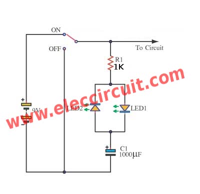
Then, we turn off S1 to “OFF” to do not use the circuit. See LED1 still goes out. But LED2 will briefly flash after that it goes out, too.
Why is that?
The 1000uF C1-Capacitor is the hero.
In the circuit, there is the SPDT switch-S1.
If we turn on, the current flow through R1 to LED1, it briefly flashes as C1 begin to charge. Until C1 is fully charging, LED1 will go out.
Since LED1 gets a reverse biased. So it is nothing that happens for LED1.
Now, C1 has the current full and there is less Leakage current.
Then, we turn off, NO the current to the output. But not end, the current in C1 discharges to LED2. It also briefly flashes. Unit the current in C1 is empty. LED2 goes out.
The LED1 goes out because it gets reverse polarity.
See look like of both LED display in video below:
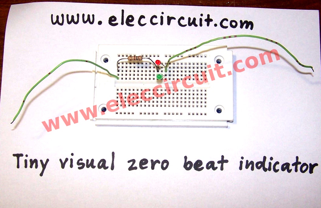
Circuit 2# Tiny visual zero beat indicator circuit
You are meeting a tiny visual zero beat indicator circuit. It is suitable for showing to an audio signal or CW tuning indicator. Which is lower than 3Vp-p.
In the circuit uses just two LEDs and one resistor only.
Light-emitting diodes(LED) LED display is the indicator. Since the LED can tolerate 20-30mA, R1 provides more than right current limiting.
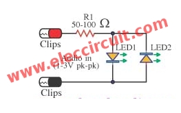
Tiny visual zero beat indicator circuit diagram
Both LEDs are connected in parallel, is a different polarity. They will indicate the zero-beat frequency.
Each LED will work just a half cycle of the input signal only.
When the input frequency is more than 1 kilohertz, away from the zero-beat frequency. Both LEDs will grow in all the time.
As the input frequency comes within about 20 hertz of zero beats, the LEDs will flicker until zero beats are reached.
Both LEDs glow or flicker until zero beat is reached, when they go out.
Circuit 3# Simple Voltage Level Indicator using Zener diode
Simple Voltage Indicator using LED and Zener diode
You look into the concept. Although is small circuits. But it might make circuits great work was complete.
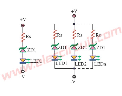
Today we come to see Voltage-Level Indicator in model easy most. It uses easy part electronics only. The Zener Diode, Resistor, and, LED as a result can show already. By in each the circuit LED stick bright when V+ goes up to arrive at Breakdown voltage. And Vz of Zener diode +VLed should use RS for LED one by one. The circuit on the right will testify to read the value is Bar Graph. When Zener Diode quietly enhance the value Vz. This circuit may is is simple good may advantage for friends, please sir.
Circuit 4# Simple three-step level indicator
Today we look at the concept of a simple level indicator circuit, which are built to be very small, can be displayed with LED 3 step. When see in the below circuit is very simple. We use a variable resistor(Potentiometer) with 3 unit only, making this the circuit cheap and easy.
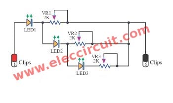
The Resistor values of Potentiometer VR1-3 are determined by the type of LED, when we used MV 50 LEDs many resistant, by steps of 2K for the 2V, and drain current (series circuits) in all three LED lights on the 5mA, the Chain LED can be extended, But the rapid increase in the drain current and the first LED in the current supply.
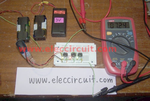
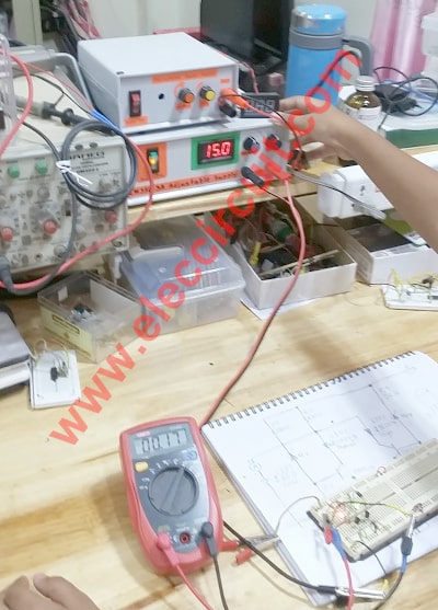
As figure below we test this circuit on breadboard with 3V for first LED1, 6V for second LED2 and 9V for third LED3.
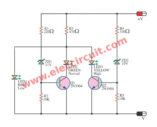
Circuit 5# Battery voltage level indicator circuit
This circuit is simple battery level indicator circuit. Which be simple complicated can see that the circuit has will LED keep for display arrive at 3 step.
The work of the circuit be this circuit was fixed come to give a temple volt usual that about 11V-14V. Which will the level volt normal, if level voltage a little 11V more make LED1 red stick bright.
Thank very much Denis this circuit error. My son is testing this circuit again and modify this new.
Thanks a lot!!
If voltage 11V more than but 14V not exceed make LED1 the red and LED2 green stick bright. Because voltage that 11V exceed have current flow through R1 and ZD1 go to encourage a pin B of Q1 make Q1 work LED2 bright. But if level voltage of power supply 15V exceed make LED 3 both of stick bright. Because of volt reed source that 15V have current flow through R4 and ZD2 go to encourage pin B of Q2, It make Q2 work LED3 , then stick bright.
When voltage is 15V up LED1,LED2,LED3 all light up. The LED1 is normal because lower current pass through its.
Circuit 6# 12V Lead Acid battery level monitor
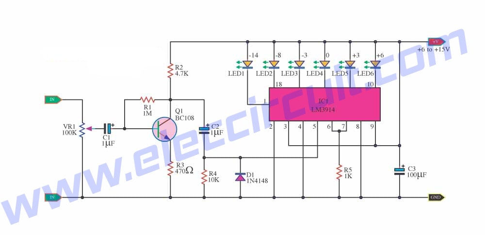
In the circuit below, a quad voltage comparator (LM3914) is used as a simple bar graph meter to indicate the charge condition of a 12 volt, lead acid battery.
A 5 volt reference voltage is connected to each of the (+) inputs of the four comparators and the (-) inputs are connected to successive points along a voltage divider.
The LEDs will illuminate when the voltage at the negative (-) input exceeds the reference voltage. Calibration can be done by adjusting the 2K potentiometer so that all four LEDs illuminate when the battery voltage is 12.7 volts, indicating full charge with no load on the battery.
At 11.7 volts, the LEDs should be off indicating a dead battery. Each LED represents an approximate 25% change in charge condition or 300 millivolts, so that 3 LEDs indicate 75%, 2 LEDs indicate 50%, etc. The actual voltages will depend on temperature conditions and battery type, wet cell, gel cell etc.
Although the circuits are is not the same. But it will help you succeed in certainly electronic projects.
Check out these related articles, too:
- 8 Low Battery Voltage Alarm indicator circuits using SCR transistor IC
- Many Simple LED AC mains voltage & current indicator circuits
- 4 Peak voltage tester circuits using op-amp and 723
GET UPDATE VIA EMAIL
I always try to make Electronics Learning Easy.
Related Posts


I love electronics. I have been learning about them through creating simple electronic circuits or small projects. And now I am also having my children do the same. Nevertheless, I hope you found the experiences we shared on this site useful and fulfilling.
Simple,,Cheap,,Useful..That’s How I like Them!!!
1 cell computer audio systems, I fear I may becoming any klipsch fanboy!
Hi,RICKY THE ELECTROGEEK
Thanks for your comment.
hi sir can you help me..will this work on a 3v battery??haw will the LED look like when battery is full,or not thank you
hi sir, how many volts for zener diode should i use for this circuit? i have 12v LA battery.
thanks!!
hi how to i find the resistor and zener diode vault if i want to make a led vu meter for a headphone?
Hi Sir,
Im a complete novice , but i need to use this simple but brilliant solution by you, I plan to connect [ 4 AAA batteries 1.6V + 9v battery ] in series.
If you could help me with what exact component [ name & specification & resistance ] should i replace in case of Rs(resistor) & ZD1,2,3 (zener diode).
Thanks a ton
Regards Santosh
hi sir,how much volt of ZD will applied for the 12volt LA battery.
Hello! This is a simple and amazing design! I was hoping I could use to to measure a maximum of 12 v! I was wondering what kind of resistors/LEDs/Zener Diodes I would need to accomplish this task?
Thank you for the design!
how do you make ambient light indicator. 2leds. both on good, 1 on medium, 1 flashing bad please sir
12VDC to 24VDC 5amp cunwert suply systems please help us urgent
Thanks
Hi Muhammad sami.
Thanks for your feedback.
THANKS , BUT WHAT SHOULD I DO IF I WANT TO MAK ONLY 12 V 2 LED POWER INDICATOR ( RED AND GREEN )??
what will be the power dessipation in zener based circuit?
i.e circuit number 1?
I want to make 6v 7mAh battery level indicator please help me and send a circuit diagram of this indicator