Here is LM386 stereo audio amplifier circuit, 2 watts. Using 3 ICs in a bridge model. It is cheap and easy to builds for a beginner.
In normal we use LM386 as a small amplifier. It can give an output power is 500mW to 700mW. But this circuit is special. The designer set the circuit is the bridge mode in a stereo system.
So, they can be saved one IC. And have power about 4 times of general OCL amplifier.
Max power of this circuit is 2 watts + 2 watts.
A basic of amplifier
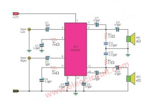
The characteristics of the general amplifier, Figure 1. Connect an output directly to a positive of a speaker and the negative terminal to the ground.
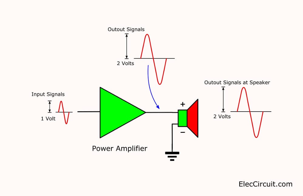
Figure 1 the normal amplifiers
And, suppose we set the gain of a power amplifier is about 2 times.
If an input signal is 1 volt, the output equals:
1-volt x 2 times = 2 volts
Remember Figure 1. What is more?
Bridged amplifier working
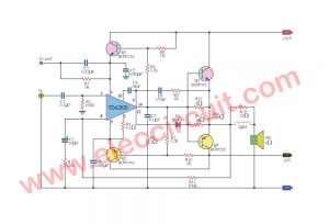
Look: Figure 2
We add the amplifier 2 into the amplifier section 2.
What the difference is between Figure1 and Figure 2?
The main feature.
- Figure 1—The gain is about 2 times only.
- Figure 2— The gain is as much as 4 times.
Which is better?
You begin interested in Figure 2, right? We called a bridge amplifier form.
Sure its power is higher loud than the first model. Some called the BTL model (Bridge output Transformerless). Advantage, not require the high voltage power supply. And can provide high power magnification.
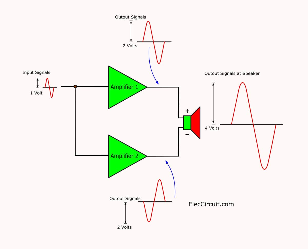
Figure 2: Basis of BTL- Bridge amplifier model
The sound from the speakers in Figure 2 is 2 times of Figure 1.
Some may wonder why bridge amplifier is high power than normal?
Both amplifiers are the same gain. But amplifier 2 works inverting phase of amplifier 1.
Imagine, it is similar we connect both batteries, different polarity. The total voltage is both batteries.
But in contrast.
Do not connect the output together. It is a short circuit until both amplifiers run too much power. Sure, they damaged.
Not only that. If we can get LM386 to build a stereo amplifier with bridge mode.
Sound good, doesn’t it?
See in the circuit below.
How circuit work
In Figure 3 is fully of LM386 stereo circuit, 2 watts.
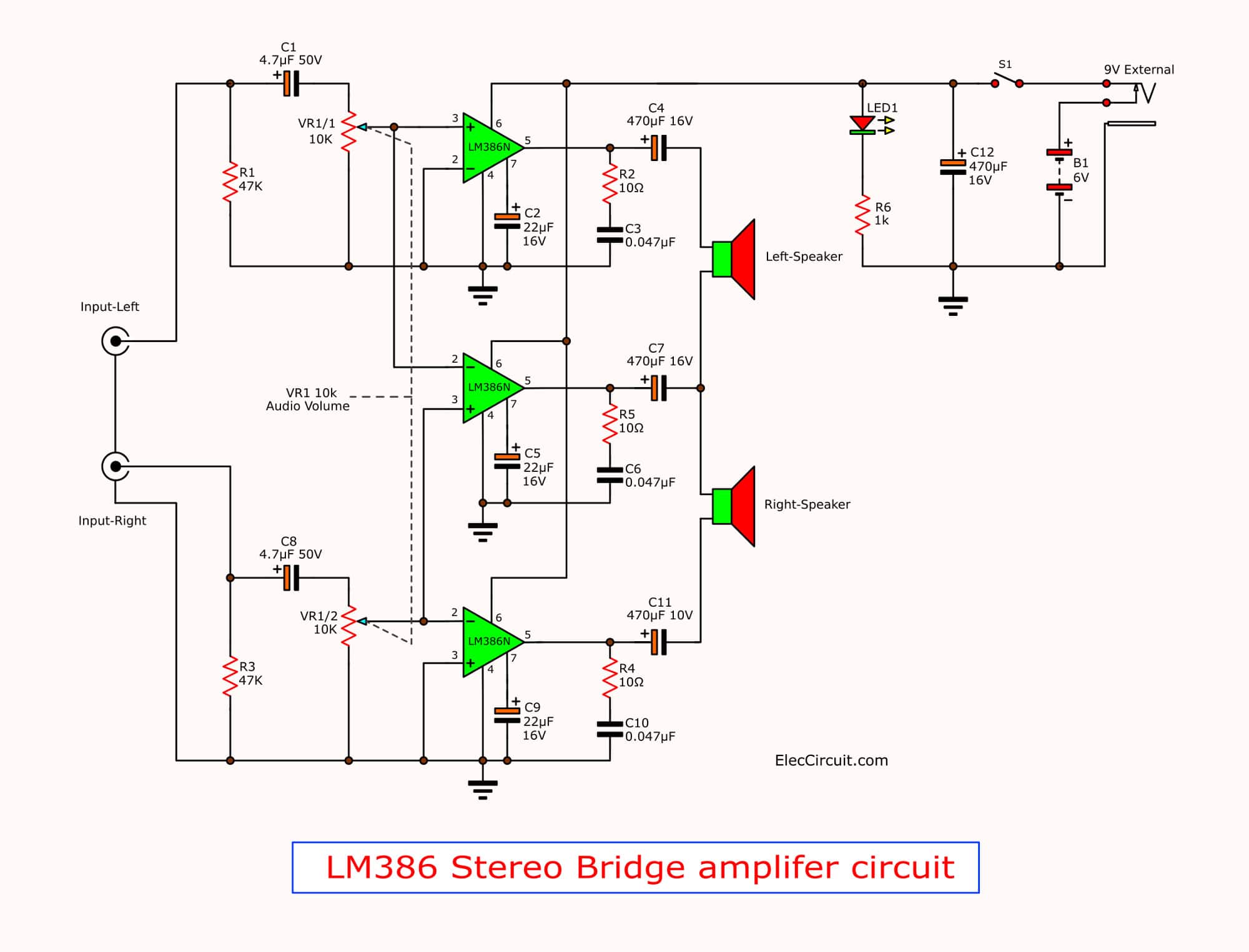
Figure 3: LM386 stereo amplifier in bridge 2 watts
Let me explain why it works in simple ways. Here is the step-by-step process.
- Apply 6V power supply to the circuit.
- Then, enter audio signals into the input.
- Adjust VR1 to turn volume up-down.
- Three IC1, IC2, and IC3 are the heart of the circuit, each IC includes resistors and capacitors connected with the appropriate values.
To give power up to 700mW to 1W (from datasheet). - Both IC1 and IC2 work together to increase the sound output to the loudspeaker, in the left channel.
- At the same times, IC2 and IC3 will work together, too. To amplifier to the right speaker. Equal to wattage is about 2 watts.
- We will see using 3 ICs each unit is 1 watt. But it was a combination of all the 4 watts. Profits of 1 watt.
Hey! This is low watts for you, right?
Look:
The parts you will need
IC1-IC3: LM386, Mini Amplifier
Resistors 0.25W, tolerance: 5%
R1, R3: 47K
R2, R4, R5: 10 ohms
R6: 1K
Electrolytic Capacitors
C1, C8: 4.7uF 50V
C2, C5, C9: 22uF 16V
C4, C7, C11, C12: 470uF 10V
Ceramic capacitors
C3, C6, C10: 0.047uF 50V
VR1: 10K (A) Potentiometer
LED1: LED as you like.
Switches, PCB, Box, wires and more.
How to builds
First of all, find all parts as the list in the circuit diagram.
This circuit use can build on the Universal PCB. Fast and Cheap.
However, if you want to use PCB layout see below.
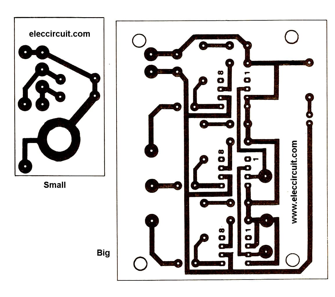
The actual size of single-side PCB layout.
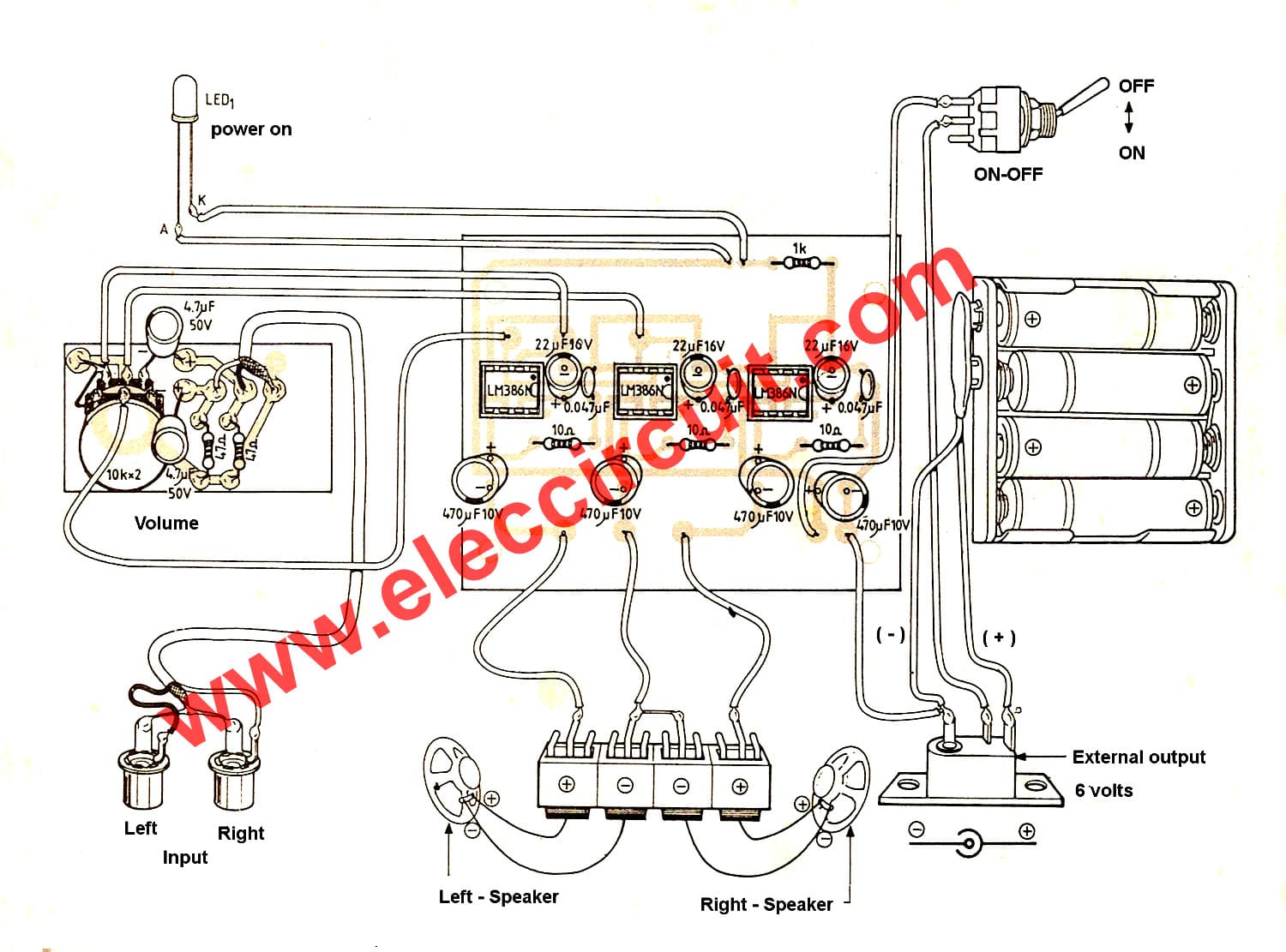
Component and wiring Layout
Here are a few related posts you may find helpful, too:
- TDA7052 amplifier | Low voltage 3V, 5V | 1 W BTL
- TDA2030 Bridge amplifier circuit
- TDA2822 stereo amplifier circuit with PCB & datasheet
GET UPDATE VIA EMAIL
I always try to make Electronics Learning Easy.

I love electronics. I have been learning about them through creating simple electronic circuits or small projects. And now I am also having my children do the same. Nevertheless, I hope you found the experiences we shared on this site useful and fulfilling.
Which is the software that you are using to generate the PCB layout.
Hi, AKHIL JOSEPH DIOUS.
Thanks for feedback.
This PCB layout is designed by illustrator Adobe 8.0
It old software for book.
can i have the pcb layout please
Hi Alex Czika,
Yes, you can. Please back to see in this again.
Have a good day.
It’s a weird circuit; I’ve been toying with this little ic’s in the pursue of more power, and did a bridge amp which sounds right with the correct speakers; I used 8″ 8 ohm sensitive speakers ( big magnet) and sounded amazingly loud for the size of the devices; with smaller ones the sound is plain deceiving; the first time I tried the circuit was with 8″ 25 ohm from an intercom and the loudness is unbeileibely loud. This little things have hard times at this pace so should be heathsinked; for my tests with 8 ohm I used 1/4″ aluminium plate with 3″ by 4 1/2″ size ( approx) mounted the ic’s carefuly against it used stripped pcb and built the cct. You may surprise the sound you can get from this little things. Someday I’ll build an entire “mini” audio system with the modules I built; I know not if I’m using 8 or 25 ohm speakers but should be well done TL enclousures with separate tweeters; The devices were fixed with a complementary piece made with the same material fixed with 1/8″ stove screws with lots of care; you won’t want to brake the ic’s either bend the aluminium locking parts.
Hi I am from Iran Reza
I wanted to remove particulate filter circuit metal detection and measurement of the volume of metal in the ground and without errors thanks
at 6v to 9v the maximum output is 500mW to 700mW per IC.
hi what is external output ?
plz reply
I’d seen this diagram and i build it.. luckily i made it but what speaker that suits in this mini amplifier?i want to use 1 woofer and 2 tweeter can you email me please..thanks
I want to purchase 200 peices audio amplifier pcb with audio jack & usb connector for giving 5v power to circuit. please contact me on 9146032723
This is Brilliant!
And i don’t see any reason why the principle can’t be used with other OpAmp-like Power ICs as well.
Thanks for sharing this idea.
Berty.
Oh, wait a moment!
What’s up with R1 and R3? Aren’t they almost shorting the input signal to ground?
Shouldn’t they be at least 47K instead of just 47 ohm?