If you want to use a small stereo audio amplifier. You may like this circuit.
They use IC – amplifier number is BA5406, 12V Dual Stereo Audio Amplifier of 3 watts + 3 watts.
This circuit is small and easy to build.
They are so suitable for expanding the use of music in a private room. Or maybe used in any experiment.
BA5406 stereo amplifier Operation
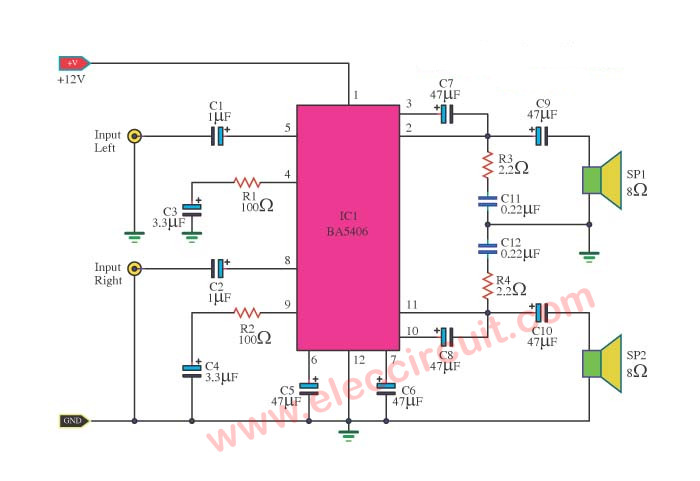
Let’s see using BA5406 circuit.
Look:
Lets me explain to you in a short text. Step by step working:
- Apply the 12V power supply to this circuit.
- Then, we enter both input signal the left and right to access pin 5 and pin 8 of BA5406.
- Which the C1 and C2 pass to coupling signal, to prevent DC to interfere in the circuit.
- We set this IC is NON-inverting Amplifier. It does not change phase output and input.
- Both output signals go out of pin 2 and pin 11 of IC.
- And that sound output signal of each channel left and right through to C9 and C10. To block DC and keep low-frequency stability.
- Then, the final signals out to both speakers.
- The C7 and C8 connect to pins 3 and pin 10 of IC, respectively.
Both pins are BootStrap to help to gain a better. - Connect C5 and C6 to pins 6 and Pin 7. They will be Filter to reduce noise from the IC.
What is more?
Read Also:
- Small IC Power Amplifier Circuits for speaker
- TDA2009 Amplifier stereo 10W | High Bridge 28 watts
- TDA7052 amplifier | Low voltage 3V, 5V | 1W BTL
Some may want to learn more about it.
See:
BA5406 Datasheet
We will see BA5406 in many application. I also see them in old appliances. For example, Radio stereo cassette player and recorders, Desktop stereo systems and Multiplexed audio for TV sets and more.
Why we should use them?
The BA5406 is dual OTL power amplifier. It includes two sets of high-power AF Amplifiers inside.
Recommended: TDA2004/TDA2005 Audio amplifier circuits
The output power is 5 watts x 2 with a 12V supply. Or 3 watts x 2 with a 9V supply.
They have features min noise when supply voltage drop.
And low RF radiation, so suited for stereo radio cassette recorders.
Not only that…See:
Special Features
- Minimal power-on pop noise.
- Immunity to supply voltage drop. (operates down to Vcc=4.5V typical).
- Excellent channel balance.
- Low distortion (THD=0.3% at
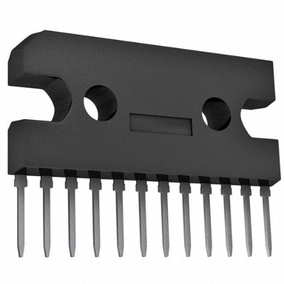
PO=O.5W). - 12 pins SIP package for mounting
easy and save space on a PCB. - Ripple filter input (pin 6) can use as a muting control input.
- The low thermal resistance of the
package makes heat-sink design
easy. - Built-in high-frequency phase compensation capacitor.
And now comes the best part:
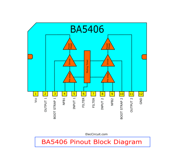
BA5406 Pinout
See the block diagram inside and pinout.
You need to know the position of various legs.
The components list
IC1: BA5406
Electrolytic capacitors
C1, C2: 1uF 50V
C3, C4: 3.3uF 50V
C5, C6, C7, C8: 47uF 25V
C9,C10: 470uF 25V
C11, C12: 0.22uF 63V, Polyester capacitors
R1,R2: 100 ohms, 0.25W 5% Resistors
R3,R4: 2.2 ohms, 0.5W 5% Resistors
Here are a few related circuits you may find helpful, too:
- How to use LM386 audio amplifier
- LM386 stereo amplifier in bridge 2 watts
- LM1875 Datasheet – 25W HIFi audio amplifier circuit
- TDA2030 stereo amplifier circuit
GET UPDATE VIA EMAIL
I always try to make Electronics Learning Easy.

I love electronics. I have been learning about them through creating simple electronic circuits or small projects. And now I am also having my children do the same. Nevertheless, I hope you found the experiences we shared on this site useful and fulfilling.

very interesting this circuit i just solve a problem by using diagrams
can i ask for the copy of the circuit desin..i want to try this.
Is this circuit is useful for low output of equalizer? And if then how much capacity (minimum) audio it amplifies for?