When we say to an astable multivibrator circuit. Most people think of IC-555. It is famous for making pulse generator and timer.
But this time, I recommended, CD4047. It is also an Astable multivibrator circuit on CMOS chip.
We can use it in many circuits. Most used in an AC inverter, Square wave generator, LED flasher, and more.
It has an advantage over 555 IC that output a 50% duty cycle and requires a wide voltage supply. (3V to 15V). Do you begin interested?
Let’s learn the basic datasheet, first!
Are you a beginner? Learn Basic Electronics
CD4047 Datasheet
Look below, it looks like CD4011 in DIP-14 form.
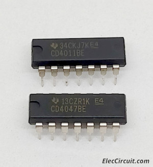
Buy CD4047 HERE
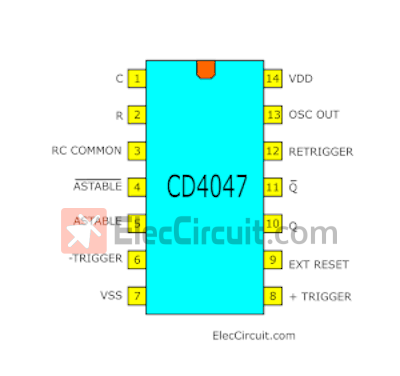
Pinout
Next step…Which leg that we enter the power supply? Where is the output pin and more, see below.
Basic Description
Then learn basic usage. See the block diagram below.
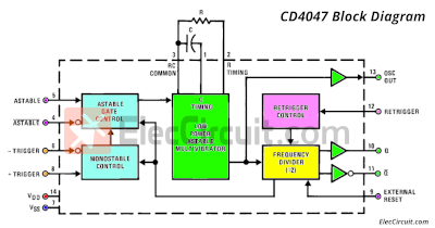
We can use the CD4047B either the monostable or astable mode. It is easy to use. With a few external components, capacitor (between pins 1 and 3) and a resistor
(between pins 2 and 3) to determine the output pulse width
in the monostable mode, and the output frequency in the
astable mode.
Learn more: http://www.fairchildsemi.com/
Features
In short
- Wide supply voltage range: 3.0V to 15V
- Noise protection: 0.45 VDD (Typical)
- Low power TTL compatibility
- Low power consumption CMOS oscillator
- Monostable (one-shot) or astable (free-running) operation
Astable Multivibrator
- Free-running operating modes
- 50% duty cycle
- Oscillator output available
- Good astable frequency stability
- Typical= ±2% + 0.03%/°C @ 100 kHz
- frequency= ±0.5% + 0.015%/°C @ 10 kHz
- deviation (circuits trimmed to frequency VDD = 10V ±10%)
Difference between 555 & CD4047
First of all, the shape is noticeably different, the NE555 has 8 pins and CD4047 has 14 pins. The CD4047 starts at 3V supply.
If the focus is on the Astable multivibrator circuit. CD4047 requires only 2 devices, Resistor, and Capacitor only.
And more importantly, it has a duty cycle at 50% in a symmetrical standard, no need for additional equipment.
It is therefore suitable for generating a set frequency in inverter circuit.
Example Circuits
I know you are interested in this CD4047. Even read a lot of information. But not clear. Let’s learn working example circuits.
Basic Square wave generator
Look at the circuit below.
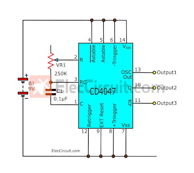
We use 9-battery is a power supply. The output will be a square wave, which has three forms are:
- I would Get The 50% duty Cycle
- Pin 13 is the basic frequency obtained by the VR1 and C1 across pins 1,2 & 3.
- Pin 10 (Q) and Pin 11(Q) shows the half frequency of the original frequency at pin 13.
- Both frequencies at pins 10 and pin 11 are inverted to each other phase. The inverted Outputs are 180 degrees out of phase.
- Three outputs have the 50% duty cycle.
Thanks: MR OHM 1970 and Hema for great information
See the waveform signal of three output.
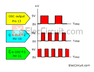
We cannot adjust the duty cycle of this circuit. It always is duty cycle of 50% that symmetry exists.
Then, we can set the frequency output by adjusting VR1 and charging C1.
The value of VR1 is used in a range of 1K to 1M. To Adjust to the desired frequency. And, the C1 will determine the frequency. The value used to determine the various range. You can see from the table below.
Note: You should pick a capacitor that has a low leakage. To reduce waveform distortion and mistake frequency.
The value of C1 in the circuit as Figure 1 to determine the frequency use.
- 1uF = 1-10Hz
- 0.1uF = 10Hz-1kHz
- 0.01uF = 100Hz-10kHz
And I use VR1 potentiometer is 250K.
How to build
This project is a few components so can put on the bread board or the universal PCB board.
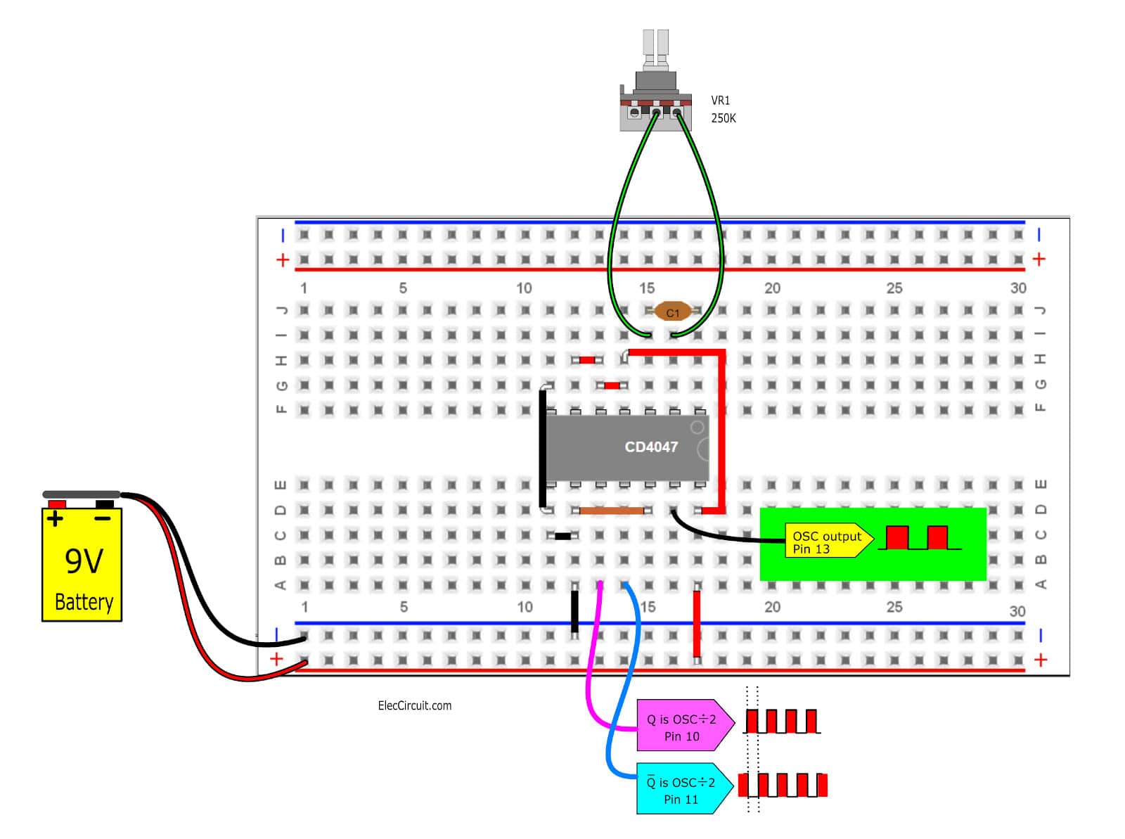
And be careful with wiring, the polarity of the electrolytic capacitors, Pin of the IC.
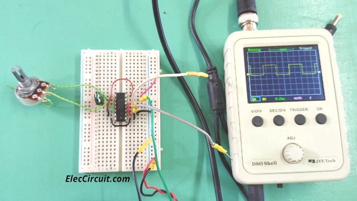
Then, measure a waveform at pin 13, pin 10, and pin 11.
The shopping lists
- VR1: The potentiometer, See in text
- C1: See in text
- Semiconductor
IC1: CD4047, Low Power Monostable Astable Multivibrator
Buy Here - Other components
Socket 14 pin, The universal PCB board.
Blinking two LEDs using CD4047
I want you to see a clearer picture of how this IC is used. Let’s build blinking two LEDs using CD4047. We used to use these circuits before, they are simple.
- LED Flashers Circuits and Projects using transistor
- IC 555 LED Flasher
- Blink 2 LED flasher using Arduino
But this IC is also easy to use. See in the circuit below.
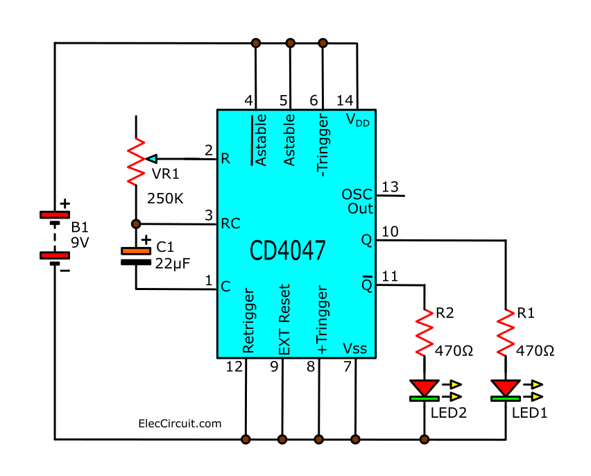
We add LED1 (Q) and LED2 (Q) having R1 and R2 limit a safe current for them.
How to build
This circuit can be built easily. We modify previous circuit. Then, add LEDs and Resistors on the breadboard as Figure below.
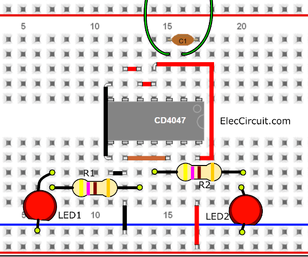
And…
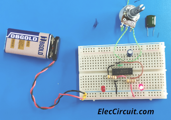
Test the Blinking LEDs circuit
I want you to try to build this circuit. For children to have fun Try changing the C1 and adjusting VR1. Notice the two LEDs blinking. Look at the video for better visualization and understanding.
Conclusion
In the past, I used the CD4047 as an astable multivibrator circuit only. Many people like to use it in this way as well. However, if in the future I use it in other ways. I will present to you again, please follow
GET UPDATE VIA EMAIL
I always try to make Electronics Learning Easy.
Related Posts


I love electronics. I have been learning about them through creating simple electronic circuits or small projects. And now I am also having my children do the same. Nevertheless, I hope you found the experiences we shared on this site useful and fulfilling.
why is it that the wave signals of pin10 and 11 are looking differently from pin13
that pin is directly connected before frequency divider
the reason is that the pin13 shows the basic frequency derived by the VR1 and C1 across pins 1,2 & 3. The pin10 & pin11 shows the half frequency of the original frequency at pin 13. the two frequencies at pins 10 & 11 are of inverted to each other phase. that is 180 degrees out of phase.
I want use this IC for inverter. may i know How to program this IC?
@RURANGIRWA BOSCO..Pin 10,11 Freq is divided by 2 @vivek The 4047 is a Cmos Multivibrator and not a PIC,,,, You can’t Program it,See 4047 Data Sheet For More Info!!! Pin 10 11 are Inverted Outputs
To determine R and C use the Formula F=1/8.8RC..I would select a Value of C and then calculate R This Formula is For The F/2 outputs whereas F output F= 1/4.4RC is for the F Output..I would use the 1/8.8RC Formula as I would Get The 50% duty Cycle!! Worked With This Chip Long Time ago
VR1 is connected beween 1 to 3 pin.
what is the difference between ic 555 and ic cd4047?
Internal circuitry is different..The 555 has a RS flip flop comparator voltage divider and several Transistors.So you can see the 555 is more like an analogue device whereas the 4047 is a digital CMOS logic gate
Thanks, my friend. It is correct and clear.
What max frequency can 4047 attain on pin 10 & 11, and for the formula f=1/(8.8*rc) should “r” be considered in ohms and capacitance in microfarad or farad. For eg. if r=1k and c=0.1 mfd.
I want the frequency in between 20khz-28Khz………..Plz……
i need help on how to built a simple inverter using irf 1407
Hi Romeo eli,
Please look at: https://www.eleccircuit.com/inverter-100w-12vdc-to-220v-by-ic-4047-irf540/
and https://www.eleccircuit.com/dc-to-ac-converter-circuit/
thank you sir,can i use irf1305 for 500w inverter -12dc to 220v
what is the advantage of cd4047 over ic555?
Hola nesecito un oscilador de potencia de 500hz a 5Mhz. Me ayudan por fabor. Desde ya muchas gracias
Kindly correct the output square waves of pin 13, 11 and 10 of Fig.1.
A wave with frequency f (at pin 13) has time-period T, while that with frequency f/2 (at pins 11 and 10) must have time-period 2T i.e. longer time periods at pin 11 and 10 than that at pin 13.
I can’t find 4047 ic. Please tell me substitute of 4047 ic.
Principal operation of ic 4011
Hello Kangume richard,
Thank you for visiting the site. I like 4011. It is CMOS chip that very useful.
I will create content about it soon. I hope you will read it.
If my voltage in a stable mode of pin14 in 12volts, what should my voltage at pin 5 of cd4047
Hello Kennedy,
Thanks for your question. Pin 5 should is “H”. or connect to 12V.
Bonjour / je pense qu’il y a une erreur dans la représentation de trois signaux de sortie de la figure 1
Hello / I think there is an error in the representation of three output signals in Figure 1
Hi bhassen
Thanks for your feedback. I just update this circuit. It is old chip. But it is so useful. I love it. Big hug!
i really need time delay relay circuit using cd4047, i don’t want to use NE555 ic because it doesn’t meet the requirement. Please help me.
Very gookd post. I am facding some oof tese issues as well..
Hello, my dear friend,
Thanks for your feedback. God bless you.