This is a 2 tone doorbell circuit, which is an electronic buzzer types, but them has melodic sound than the general electric bell. Many people have seen the two-tone bell sounds in other electronic journals.
1# Simple Doorbell circuit using transistor
But they are circuit that made no who apply them, since Problems three reasons:
1.First, while do not press a switch, the circuit also still have a lot of current consumption around up to several tens of milliamperes.
If will make on-off switcher, a power supply of circuit will must add other one switch individually. When we will press the buzzer we must press the other switch before, then when press completely the buzzer switch, we must close power switch again. To set to application as begin.
2. Secondly, the output sound is real two level. But the sound is vibrant and clear.
3. Thirdly, Suppose that solving the problem on-off switch,with replace an old battery with a DC adapter to circuit.
But the providing the power supply to circuit all the time that may making IC has heat and fast damaged, because those circuit use IC as the sound generator and they have more many cost than transistors.
So some companies ever produced a two tone buzzer kit to sell. But now out of production to Because of Problems mentioned above.
But for this two tone door buzzer that I would like to introduce you build them, which as circuit are designed become to solve all those.
If you do not press the buzzer switch, the circuit will not use the Low power consumption, by not must have on-off switch individual. And though while press the buzzer switch, the circuit will use low current so long time apply though is use by the normal battery.
Another issue, the circuit is designed to use all the transistors. In addition will clear, melodious and resonant voice. And creating cost savings as well. Because the transistors has very cheaper than ICs.
The working principle of circuit
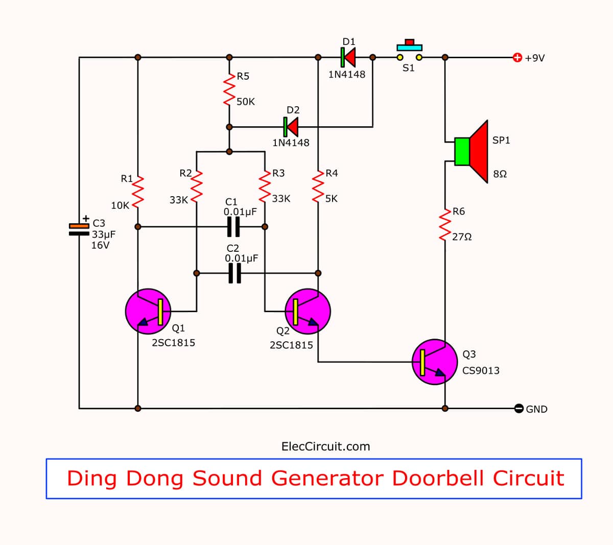
In-circuit diagram as Figure 1 will see that we use both transistor are connecting as the oscillator circuit on multi vibrator form. To crease a square wave signal then send to amplify in the next transistor before, to provide the signal high up then enter to the speaker.
Observe the circuit to generate the sound. Sound frequency is determined by the value of Resistors and Capacitors. Here we use the C-0.01uF is constant.
Read also: How does a transistor circuit work
So if we change the value of Resistors, Frequency of sound will go to change. Which Resistors in circuit has two set are R-33K quantity = 2 pcs. And Resistors R-50K other one.
While when we press switch, which is the pushbotton switch, current will flow through separated into two ways.
First way, flow through Diode-D1 go to charge in the capacitor-33uF 10V and while is also supply the current to Collector lead of both transistors.
Final ways, current will flow through diode-D2 in to common joint of R-33K to bias to base lead of both transistors.
In while both transistors will can oscillate, because have fully bias and frequency that get from usage this resistor-33K will be 2,200 Hz amplify out of speaker into high frequencies.
When we release the switch will no current flowing through both diode but will also has some current that still charge in capacitor-33uF 10V.
Which it will discharge out of the power supply to the oscillator circuit. But in while current in the base circuit will pass both resistors-33K and 50K are mixed into 83K. When they have high resistance cause low frequency, from Calculated to be approximately 800 Hz. And This capacitor of 33uF 10V will fully discharge within time about 1.5 seconds. The oscillator will stop working,the speaker will go silent.
I concluded that, when press switch will be sound at frequencies of 2,200 HZ
Switch is released, it will sound frequency of 800 Hz is about 1.5 second. So, we will have the two tone door buzzer as you need.
Read: Make Simple Electronic Buzzer circuit
The building and application
This circuit have a printed circuit board copper foil track layout of this project. (actual-size) as Figure 2, For building also still same general circuit (as Figure 3) is put a low components before example: Resistors, Diode, Capacitors, Transistors sequence.
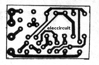
Figure 2 Actual-size,Single-sided PCB layout
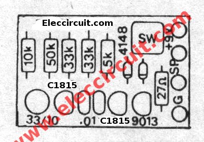
Figure 3 the top bottom components layout.
The speaker is used with size of 2 inchs 8 ohms 0.25 W to The compact But it applies to the other sizes.
This circuit use 9 volts power supply, All resistors use size ¼ W, switch use pushbutton types,and transistors; use number C1815,C828, or others NPN transistors. other parts see in circuits.
Parts you will need
Q1,Q2: 2SC1815,2SC828,2SC458, NPN transistors
Q3: CS9013, 40V 0.5A NPN transistor
C3: 33uF 16V Electrolytic
C1,C2: 0.01uF 50V Ceramic
0.25W Resistors, 5% Tolerance
R1: 10K
R2, R3: 33K
R4: 5K
R5: 50K
R6: 27 ohms
D1,D2: 1N4148
These are many simple door buzzer circuits, use low voltage so safely.
I fall bored old buzzer. When using the AC line, the danger of leakage power in the heavy rain.
Three Circuits Below can help you! What is more?
Have you ever had a problem with the front doorbell or not?
When used with directly AC line, the danger of leakage power in the heavy rain.
And the doorbell quality is very expensive.
I think we try to make ourselves better, strange sounds are unique. Cheap pieces of equipment. And high performance. Because we have a Choose circuit.
I collected many of the circuits as follows.
Learn: How does NE555 timer circuit work
2# Doorbell circuit diagram using 555
This is an easy buzzer circuit. It uses IC 555 timer as key, Speaker 25 -80 Ω.
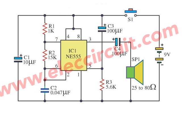
I demolish a store-room, see old loudspeaker, and other equipment a little again. Then born the though builds Door Buzzer by use, IC 555. Perform sound electric bell origin.
When press S1, as a result, have a voice fair loud. This circuit almost must not do anything.
Because divisible Amen! should use 25-80 Ω size loudspeakers. It will make good sound use force against electricity low work or economize the electricity. You will use 9V batteries all right.
Also: Simple time Delay Circuit using MOSFET
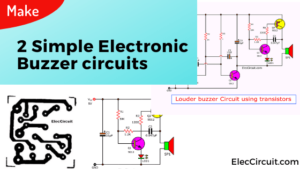
3# doorbell circuit using NE555 and LM386
Someday I go to visit a friend. He begs me for helps to seek an electric bell front door circuit. In the model to be simple, use a little equipment.
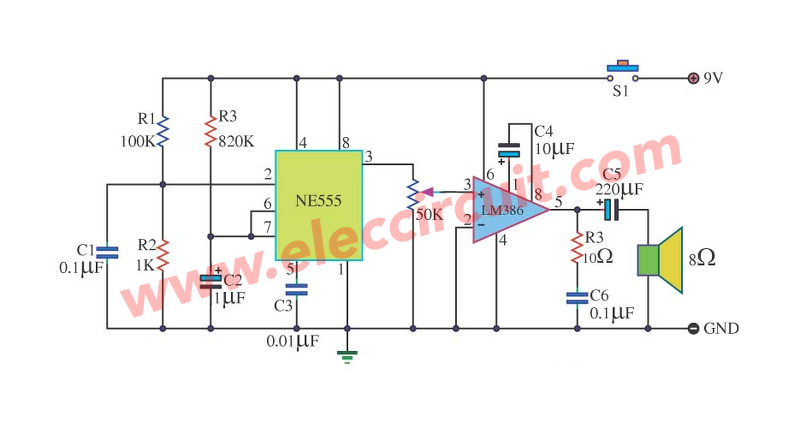
I then choose the Door Buzzer circuit this give. Because of use, IC NE555 produces electric bell sound and uses IC-LM386 to amplify talk at one time. For R1 use fine decorate the sound as you like it. request have fun with this circuit.
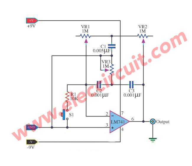
4# Simple Electronic Bell Generator using LM741
This is a basic electronic ell circuit, it is interesting. We use a number of IC-741 Op-amp, it works. When you press S1 will be mimic the bell sound at the output pin 6 of IC1, which we can fine tone sound with three potentiometer are VR1-1M, VR2-1M and VR3-1M to control sound as close as possible. We set form of the audio oscillator generator or sine wave form can be changed with by pressing our S1. But sound is slight required to use power amplifier for boost up its. And this circuit need the dual power supply positive, ground, and negative 9V power supply.
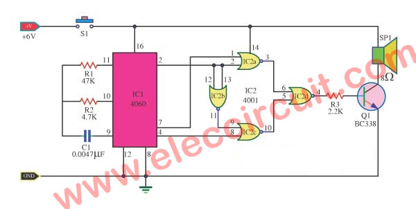
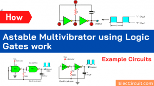
4# Doorbell circuit using CD4001-CD4060
We like The Door buzzer sound circuit, in two-tone sound. It uses a low voltage, 6V power supply so it is safer than general AC main. We can install the push button outdoor, do not worry about rainy to makes a short circuit. It saves if you use a battery. Because it uses energy only press the push button. See the advantages, do not wait! You can build it.
How it works
When we press the switch-S1. An electric current flows to the circuit. The IC1 will makes two things.
- First, generates a oscillator in high frequency. Which the C1 and R1 set a frequency level.
- Second, it will divide frequency to lower into the tones.
This audio signal from pin 7 and pin 4 into the pin 1 and pin 8 of the IC2a, IC2c respectively.
The IC2b of a frequency converter to control IC2c. When the control signal in during the low state (Low), The 1.25 kHz frequency will come to IC2a.
At the same time, the control signal flows through IC2b to be a high state (High).
The 300 Hz frequency will come to the IC2c. Also, the output at pin 3 of IC2a is low in the same condition.
The output of IC2a and IC2c output is sent to the IC2d. Which it mixes both signal to output to the transistor-Q1.
The Q1 acts as switches and amplifiers. The tones can be heard as two strokes.
The R3 acts as a volume.—You add more value to make the softer sound, but it is lower.
This circuit uses a 6V power supply. You should use a 6V battery or 1.5V x 4 batteries.
How to build this project
You can build easily circuit. We use the universal PCB board because has a few parts Cause faster for making than a general PCB.
The component List
IC1: CD4060, 14 stage ripple counter, and oscillator IC
IC2: CD4001, Quad 2-Input NOR(NAND) Buffered B Series Gate
Q1: BC338, 0.5A 50V NPN transistors.
S1: Switch Normally opens the pushbutton.
C1: 0.0047uF 50V, Ceramic capacitors.
R1: 47K Resistor
R2: 4.7K Resistor
R3: 2.2K Resistor
GET UPDATE VIA EMAIL
I always try to make Electronics Learning Easy.
Related Posts

I love electronic circuit. I will collect a lot circuit electronic for teach my son and are useful for everyone.
You provide good circuits & some r intresting & easy to assemble.Keep it up./
i am the student of 3rd year B.tech electronic and communication branch.i am making the project power generation using speed breaker with the help oh piezoelectric buzzer.please provide me the circuit for this…….i will be highly obliged…..
Please i have been trying build the salt and alkaline tester as well as the door buzzers there are not working properly. I need them for my project. Thanks
Hai sir,iam the student of 3rd year b.tech student,sir,i want some electronic mini projects,so,could you please send me that mini projects sir
simplified and straightfoward circuits .
Hello sir, i thank you for the good work that you have been doing. Do keep it up. I am just a beginner in electronic career from Nigeria and your site have been very helpful. Please help me with what ever informaion you can …thanks a lot.
Hello,Emly
Thanks for your feedback.
sir can u plz tell me what are the applications of buzzer circuit
Dear sir am very grateful for your good works in engineering
Are there any 1 second long buzzers?
FUN DOOR BELL CIRCUIT, AMAZES CALLERS.
I have just perfected a circuit which, when the door button is pushed and released the sound will continue to sound for 2 to 10 seconds. The tone produced makes variable sounds as the energised capacitor when the bell push is pressed, gradually loses its power after the button is released. The time the speaker sounds is adjustable from 2 to about 12 seconds depending on the value of the capacitor. The circuit will run 3 loud- speakers placed in different locations, which all make the same conglomoration of notes produced. THE CIRCUIT WAS BUILT USING COMMON TRANSISTORS ONLY, AND NO I.Cs, Cost was about £6 excluding the case to house it. HL.
“FUN DOOR BELL CIRCUIT, AMAZES CALLERS” – Can you please post the schematic and any more info about the circuit, or email it to me? Thanks!
Right here is the right web site for anybody who wants to understand this topic.
You know so much its almost hard to argue with you (not that I really will need to…HaHa).
You certainly put a new spin on a topic that has been discussed
for many years. Great stuff, just excellent!
i have simulated this doorbell circuit in ltspice and it doesn’t work. There are no oscillations. It’s as if the 33u capacitor doesn’t need to be there at all!