ECG simulator circuit is very useful in the medical community. Such as experimental research and development of biomedical imaging.
But we should do not use this with patients. Because we do not want that. The real purpose is to preview a heart rate only.
In general, measuring the rate of the heartbeat will get a waveform as Figure 1.
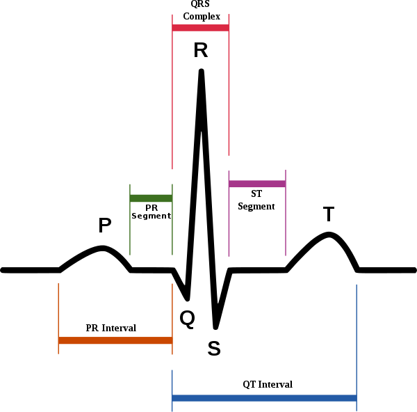
Figure1 the ECG waveform and feature of P to U
CR: https://en.wikipedia.org/wiki/Automated_ECG_interpretation
Start of all, we take the sensor to Attached to on the patient at various points.
Measurement results are the amplitude of approximately 1mV.
A heartbeat rate is between 40 Hz to 150 Hz.
The electronic medical use the letter P to the U to count the ECG wave is 1 time. We will see one waveform include the one peaks of spikes.
The working of circuit
The circuit consists of two standard logic ICs and a few parts.
IC1-CD4521 is a CMOS IC called a 24 stage binary counter. It has the frequency setting in the counter is X1-crystal at a frequency of 4,194,304 Hz.
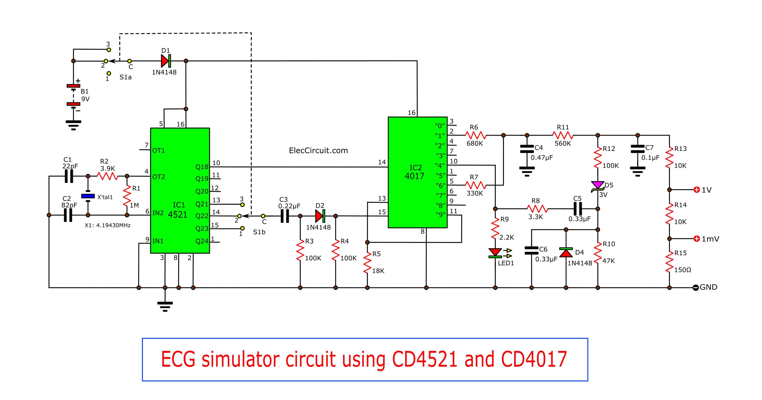
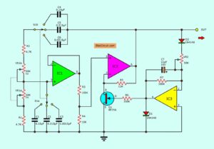
Figure 2 ECG simulator circuit using CD4521 and CD4017
The IC1 will divide frequency out of 16 Hz. Its output is a square wave to output Q18 (pin 10).
And, S1b is selector switch to choose the output frequency of IC 1 is a low frequency of 1Hz or 2 Hz.
Then, the 16 Hz output frequency is a clock signal. It gets into IC2, CD4017.
Which the 4017 is good at a Decimal Counter circuit. Next, see in the circuit at pin 15 of IC2 to divide frequency at output 10.
After that, The second signal will be filtered with R3 and C3. They are a waveform in spikes into pin 15 of IC2. Then, D2-diode will block a negative voltage not flow into pin 15.
And, IC2 will count to 9 and on hold this state. And, pin 11 connects with pin enable input (pin 13) to reset working. Which it is the wave conditions in the U form.
If necessary, you cannot find Crystal as specified. You may use 4MHz instead, but the frequency will be slightly distorted.
Also, we watch at the output devices. Which they get an output signal of Q1, Q4, and Q6.
By the first wave is a pulse that has been transformed into a P waveform, by the filter in integrator form. They include of R6 and C4. The C4 will charge from 0V to about 1V.
For T waveform, we get it from the integrator of R7 and C4. The R7 is the resistance of less than half of the R6. And the pulse waveform of Q6 will charge more up.
Which C4 are 2 times of the P waveform. C5 and R10 are put into an R pulse between 2 waveforms.
Then, The R8-resistor to limit the current to the charging of C5. And in at the same time, D5 allows the voltage to 3.8V via the C R9 and D3.
And, LED blinks while the R-waveforms.
Then, the spike waveform passed R13, R14 and R15 will convert the output voltage is 1V and 1mV as we need.
This circuit uses the 9-volt battery. And, The rate of consumption of the circuit about 2.5mA.
Before Build it
I publish this circuit. Because of the benefits of medical. But I never tried it at all. So I can’t confirm that Is it works? I sincerely apologize.
Okay, friends, You are smart! you want to try it for everyone.
I suggest you assemble the parts on a universal PCB. Then check all for errors after assembling them. Next, connect the wiring to the oscilloscope and the battery wire to the circuit. Just now already to use ECG simulator.
The component List
Resistors 0.25 W 5%
R1: 1M
R2: 3.9K
R3, R4, R12: 100K
R5: 18K
R6: 680K
R7: 330K
R8: 3.3K
R9: 2.2K
R10: 47K
R11: 560K
R13, R14: 10K
R15: 150Ω
Capacitors
C1: 82pF 50V, Ceramic
C2: 22pF 50V, Ceramic
C3: 0.22uF 63V, Polyester
C4: 0.47uF 63V, Polyester
C5, C6: 0.33uF 63V Polyester
C7: 0.1uF 63V Polyester
Semiconductors
D1, D2, D4: 1N4148 0.75A 100V_Silicon Diode
D3: LED_in Super bright type
D5: Zener Diode_3V 500mw
IC1: CD4521__CMOS 4-stage Frequency Divider
IC2: CD4017__DECADE COUNTER/DIVIDER IC
Others
S1: Slide switch in DPDT – Double – pole , Double-throw.
BT1: 9-volts battery
X1: Crystal__4.194304 MHz
GET UPDATE VIA EMAIL
I always try to make Electronics Learning Easy.
Related Posts

I love electronics. I have been learning about them through creating simple electronic circuits or small projects. And now I am also having my children do the same. Nevertheless, I hope you found the experiences we shared on this site useful and fulfilling.
Can you tell me of any problems you had with this circuit and can you show me some calculations for designing the circuit
Please can you tell me which simulator logiciel you are using, i didn’t find the IC1 “CD4521” in ISIS proteus.
Hey av used most of your circuits and they helps me much thanks.
Hi, simon
Thanks for your feedback.
MAY I KNOW HOW TO INJECT THIS SIMULATOR TO THE ECG MACHINE. THANKS.. IS THERE ANY FINAL ASSEMBLY FOR THIS DESIGN?
may i know which simulator logic that you are using . i didnt find the IC1 “CD4521” in ISIS proteus.
Happly all people think about sw ignoring the glorious time of hd. The comments are typical for people will never integrate the symbiosis between complements.
Although the simplicity of you circuit please receive the congratulations from an electronic engineer 78 yo
rui figueiredo
I need the proteus library for the following components. is there anyone who can help me, please?
Component1 ID : CD4521
Component family: HEF or HEC
function: 24 stage frequency divider and oscillator
Type: integrated circuit
######################
Component1 ID : CD4017
Component family: HCF or HCC
function: decade counter or devider IC
Type: integrated circuit
EWUNATE ASSAYE KASSAW
Thanks for your visit. I am happy that you are interested in this circuit.
Do you want to learn about datasheets of CD4521 and CD4017?
See CD4017 datasheet and example circuits.
https://www.eleccircuit.com/ic-4017-datasheet/
And see CD4521
https://www.ti.com/lit/ds/symlink/cd4521b.pdf?ts=1610595472825&ref_url=https%253A%252F%252Fwww.datasheets360.com%252Fpdf%252F4115822798733540962%253Fquery%253DCD4521%2526pqid%253D107399962
If you would like to others detail. Please tell me. I like to help you love electronics.
Thanks
Apichet
can you share the library proteus for the ic 4017 and ic 4521 ?
Hello MUHAMMAD ASRAF BIN MOKHTAR,
Please see: https://www.eleccircuit.com/ic-4017-datasheet/
But I am sorry. Now, I do not have the 4521 datasheets.
Thanks
Thanks for the Schematics and the explanation how it works. I created the configuration on the breadboard. I must say it didn’t work for me at first. The last stage of the circuit is not working.
If you remove C7 capacitor and remove R13, R14 and R15 and you will see like a nice ECG with a Vpp of 1.7V . The C7 capacitor filter the QRS wave, which is not the idea (so I removed C7). I think you need to create an end stage buffer circuit (Opamp), to get a lower impedance output (to provide real 1V and 1mV). Now these output divider resistors (to output 1V, 1mV) pulls the ECG signal down at the crossing position R11/R12.
Hello
Thanks for your visit to my site. You are a good electronic man.
I am sorry to hear that it does not work.
However, I have always believed that learning from mistakes is the best of learning, it is always one step toward success. I noticed from your message. You are a great experimenter. You will surely succeed, I believe you.
Have a good day.
Apichet