These pulse generator circuits—a.k.a. an astable multivibrator oscillator circuit—employ a 555 timer IC, NE555 or LM555, in its astable (free-running) mode. These types of circuits are often paired up with digital logic circuits.
The 555 timer IC is also very popular and simple to use, with a small eight-pin package and a supply voltage range of 4.5V to 16V. In addition, the current consumption is 3mA at 5V, with a maximum output current of 200mA, and a maximum output frequency of 1MHz.
The 555 timer IC can be used in a variety of ways, including as an oscillator, which comes in three types:
(1) Astable multivibrator—continuously switches between two unstable states, hence “a” in the term astable.
(2) Monostable multivibrator—one state is stable but, when triggered, switches to an unstable state for a set period of time before returning to the stable state.
However, today we will only cover the astable or free-running mode of the 555 IC, which we will learn about using a collection of example circuits below.
Simple 555 Timer Astable Oscillator Circuit
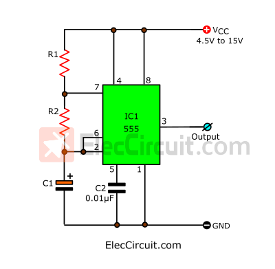
First, let’s start with the most basic pulse generator circuit.
How It Works
First, the current from the power supply flows through resistors R1 and R2 into the capacitor C1, charging it up. Then, when the voltage inside the capacitor reaches two-thirds that of the power supply, the IC1 detects it through pin 6 and internally connects pin 7 to the ground.
This allows the C1 to discharge through the R2, but when the remaining voltage is one-third that of the power supply, pin 2 detects it and disconnects pin 7 from the ground. The C1 will charge up again and the cycle repeated.
The R1 protects the IC from damage when pin 7 is shorts with the ground. Its resistance is very low, thus it would not have any significant impact on the timing of the oscillator.
The formula for the output frequency is F = 1 ÷ {(R1 + 2R2) × C1}.
The units in the formula are ohms, farads, and hertz. This formula only concerns the output frequency and does not take into account the duty cycle.
Suppose R1 = 1K, R2 = 10K, and C1 = 0.1μF; the resulting frequency is approximately 900Hz.
Parts List
R1: 100K, 0.25W resistor tolerance: 5%
R2: 10K, 0.25W resistor tolerance: 5%
C1: 0.1uF 50V Ceramic Capacitors
C2: 0.01uF 50V Ceramic Capacitors
IC1: NE555 Timer
Read also: 555 timer audio alarm circuits
High Power 555 Pulse Generator
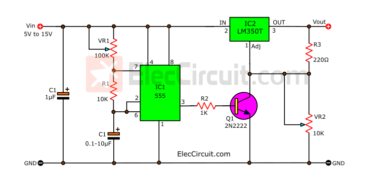
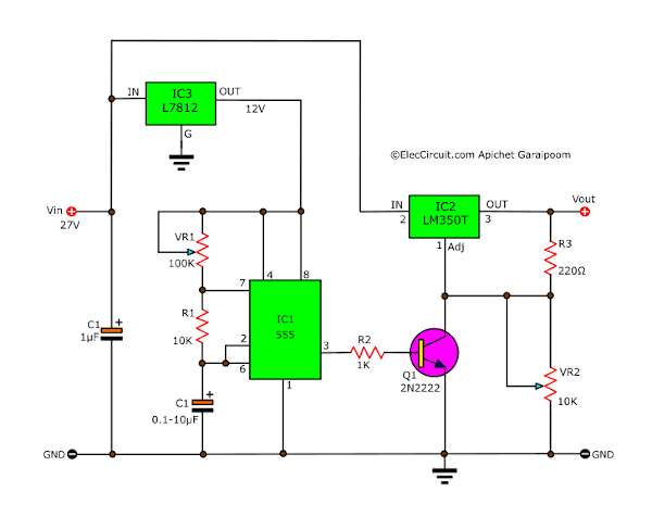
This high-power pulse generator circuit is a great fit if you’re looking for a pulse oscillator that can output a high current. It uses a 555 timer IC as the oscillator, and an LM350T amplifies the current up to 3A.
How It Works
The 555 timer IC by itself can only output a maximum current of 200mA, like the Simple 555 Timer Astable Oscillator Circuit above. However, the output current can be amplified after the fact to our desired value. In this case, we will be aiming for 3A.
At first, we thought about using a 2N3055 power transistor to amplify the current. But we went with an LM350T regulator IC instead. It is a 3A DC regulator and a better choice as it has a higher performance than the 2N3055.
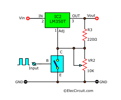
The above circuit is a basic LM350 regulator circuit that we are already familiar with. The VR2 is used to adjust the output voltage as desired. The Q1 between Adj and GND works as a switch controlled by an input pulse signal through its B.
The oscillator in this circuit is still the NE555 timer IC. It generates a square wave signal, and the frequency is adjustable through the VR1.
The square-wave signal from IC1’s output enters B of the Q1 transistor. The Q1 uses that signal to control IC2, and thus the output of the circuit.
The Operating Sequence
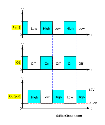
When the output of the IC1 is in a ‘low’ state, the Q1 does not receive the base current and therefore does not function (off). This means that the adj of the IC2 is disconnected from the ground, causing the output voltage to be as set by the VR2, in this case 12V, or is in a ‘high’ state.
When the IC1’s output is in a ‘high’ state, the Q1 will operate (on) and connect the adj of the IC2 to the ground, which by default causes the output voltage of the IC2 to be 1.2V, or is in a ‘low’ state.
To put it simply, the Q1 translates the output signal of the timer IC into an order for the regulator IC to operate and control the output of the circuit, practically isolating the regulator part and the pulse generator part of the circuit. The circuit output voltage state is the inverting of the 555 timer IC’s output.
Increasing the Voltage
This circuit requires a supply voltage of 5V to 15V because the 555 timer IC can only operate within this voltage range. However, the LM350T’s output is approximately 2-3V lower than its input, meaning that the overall circuit output will be between 3V and 12V.
Nevertheless, if you need more output voltage, such as for a 24V DC motor, you can increase the input voltage to 27V, which is still within the LM350T’s specification of 37V, and add a regulator circuit to reduce the voltage before the IC1, such as a 7812 chip for a 12V supply.
Also, if you only need 1.5A, you could use the less expensive LM317T regulator IC instead of the LM350T.
Pulse Generator with Digital Frequency Controller
Next, let’s look into the idea of using a digital logic to control the 555 pulse generator circuit frequencies.
As we have learned before, the capacitor’s capacitance has a direct impact on the output frequency (F). So, based on this idea, we created the following simple four-selectable-frequency pulse generator circuit.
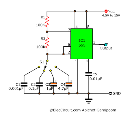
The S1—a single-pole, four-position rotary selector switch—switches between the four capacitors, causing the output frequency to change with each selected capacitor. The output frequency from each capacitor is as follows:
- C1: 4.8KHz
- C2: 48Hz
- C3: 4.8Hz
- C4: 1Hz
But what if we want to use digital data to control the output frequency instead of turning the switch on our own? In that case, the best bet is the CD4066; we will be using it as a data selector circuit.
CD4066 Bilateral Switch
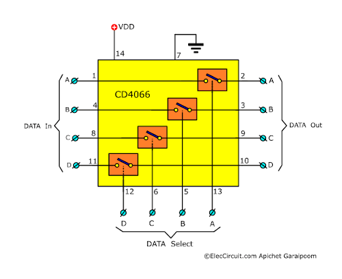
The CD4066 quad bilateral switch is a very popular and widely used chip. It has internal four analog switches, each controlled by a different control pin.
When the control pin is connected to the VDD (high-state power pin 14), the corresponding internal switch’s resistance is significantly reduced to about 80 to 250Ω. This indicates that the switch has turned on or closed the circuit.
But on the other hand, when the control pin is connected to the VSS (low-state power pin 7), the switch’s resistance is greatly increased to around 10M. This means that the switch has now turned off or opened the circuit.
Do note that each set of input, output, and control pins works independently of the other. Also, as with a normal switch, the input and output are not polarized and can be switched around.
One of the great points of this IC is that it’s a digital IC, which means that it has higher accuracy and works faster than regular switches and relays. However, it is a CMOS chip and thus can only withstand a minimum amount of current.
The Complete Circuit
And now we combine the CD4066 with the circuit above.
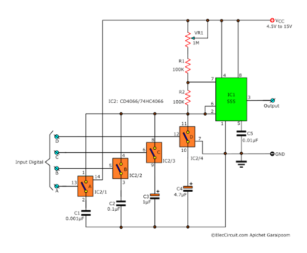
The CD4006 in this circuit functions similarly to the rotary selector switch. For instance, it connects to the capacitors (C1-C4) to choose the output frequency.
So, if we apply a high-state voltage (logic ‘1’) to any of the control pins 13, 5, 6, or 12, the switch will make contact and connect the corresponding capacitors to pins 2 and 6 of the IC1.
Sometimes, if more than one control pin receives logic ‘1’ simultaneously, the capacitors will be in parallel with one another. As a result, the total capacitance increases, thus lowering the output frequency.
Aside from that, if we want to change the range of the output frequency, we can simply adjust VR1. Moreover, we can even change the resistances R1 and R2.
Conclusion
As you may have seen, the 555 chip functions well as the core of a pulse generator circuit. These example circuits that I bring up are only the tip of the iceberg. This chip will undoubtedly have a wide range of applications. In the future, I might talk about the OP-AMP pulse generator circuit as well. Normally, these OP-AMPs specialize in amplifying signals. However, we can use them in a pulse generator role as well.
GET UPDATE VIA EMAIL
I always try to make Electronics Learning Easy.
Related Posts

I love electronics. I have been learning about them through creating simple electronic circuits or small projects. And now I am also having my children do the same. Nevertheless, I hope you found the experiences we shared on this site useful and fulfilling.
very nice & good service i hope people will happy with service
Hi, abdul
Thanks you.
I need a 555 circuit that must be triggered on by a switch and stay on for about 20 seconds.
Will you email me a diagram how to do that?
I need a sch. of an astable 555 with an on time of .75sec., a dwn time of 5sec, or there abouts. All I need is values of r1, r2 and c1. Can you help me?
I would greatly appreciate it.
Bob W.
special thanks!
very very nice sit!
i need clock pulse for counter circuit for increment by one counter ic 74hc393 so please tell me how can i do……
I want a pulse generator. That must be get more output pulse .Please help me.
I need a 555 circuit that must be triggered on by a switch and stay on for about 20 seconds.
Will you email me a diagram how to do that?
Your site and projects are awesome.You are teaching me electronics the no one could.
Thanks
Paul Perold
Cape town
South Africa
which is R1?
Hi,
I am sorry for late answer you.
R1 = VR1
This is simple circuit.
Hi,Paul
Thanks for your feedback.
each time i used to read smaller posts that as well clear their motive, and that is also
happening with this post which I am reading at this time.
I want a pulse generator for time period of about 0.5sec please mail me the circuit. And further details of it
i want to replace ic mm 5369 with ic 555 in my digital clock using mm 5387 clock chip.please give me a circuit for this purpose.Presently it runs on 12v dc.the ic mm 5369 is not available so please help me.
hi what values should I use to make a 8hz oscillator somewhere near schumann resonance?
some componet failure any iam don’t identify
2 qustin
1. duplicate component
2. Circuit wrong connected
Hi Solo
Thanks for your feedback.
This circuit is correct.
What cap did you used? Ceramic or mylar? Thanks btw
Hi Masterlogic,
Thanks for your feedback.
You can use both ceramic and mylar capacitor. or MKP or MKT that good capacitor which is expensive type.
momename, can you create a variable frequency clock pulse that varies from 1Hz to 60Hz. Can you send it to my email? I badly need it. Thanks and more power. 😀
Hi MasterLogic,
Thanks your feedback.
This circuit can also be used to create a variable frequency clock pulse as you need.
or https://www.eleccircuit.com/time-based-clock-generator-using-crystal-for-digital/
Thank you man! I really appreciate it. More power 🙂
You are welcome.
Looking for a simple pulse generator to build or buy for experimental work.please advise on who can assist, Regards
If the circuit is implemented without using 555 timer ic; then we need to use comparators, SR latch and transistor. So how would the two circuits differ if SR latch is implemented using NAND gates or NOR gates?
hi,
I would like to know explanation about this circuit.
what is the maximum range of frequency can we generate using this circuit?
Is it possible to generate 4.3MHZ?
i have 2 firing circuit for mosfet which is generated by ic 555,how i can obtained ac output from this
There is a huge fault in this circuit. don’t post circuit that you have not built.
Is it possible to place a potentiometer instead of the resistor to make a variable frequency? How would one go about varying the power in this circuit?
Hi Felix
Thanks for your question.
You can use them.
Hi there,I log on to your new stuff named “Simple Pulse Generator circuit by IC 555 Timer” like every week.Your writing style is awesome, keep up the good work! And you can look our website about proxy list.
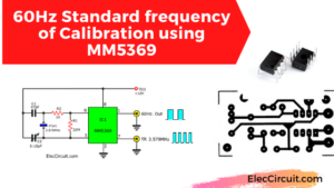
OBJECTIVE
Drive an ignition coil at 60Hz from a 12V lead acid battery.
IDEA
I have built the 60Hz calibration frequency standards for digital clock by MM5369 (fig.1) circuit and found that it only put out 5.3V at 250mA but the trigger for the Cdi needs 12V now I understand why the LM350 circuit was recommend (I’m a little thick sometimes lol but I did learn).
What I am wondering is could I substitute the digital clock MM5369 (fig.1) for the 555 timer in high power 555 pulse generator (fig.2)? Some considerations I am wondering about are – in fig.2 I imagine I will still need C2 -1uF and R2 -1K but what would I need to do to get the output voltage (R3 but referred to as R5?) to 12V?
I am hoping to be able to send the signal at 12V 1 amp. with LM317T to the Cdi and be able to tune the circuit to 60Hz if deviation occurs.
Thank you for your time and any insight would be greatly appreciated.