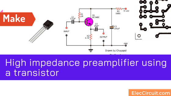
If we want a high impedance preamplifier circuit. Because we use a crystal microphone or we use it with a ceramic record player, etc. These devices require the input of a high impedance amplifier.
This circuit also has a low damping value. Make the sound come out concisely.
Of course, we like choosing simple and cheap circuits, this circuit too.
See the active circuits below. It’s a simple circuit. With only one transistor, original characteristics.
Note: This circuit is one of 4 transistor preamplifier circuits. All circuits have PCB so easy to learn and having fun.
- Low impedance input Preamplifier
- The medium Impedance Preamplifier circuit
- High Impedance Preamplifier circuit
- Simple Preamplifier using FET
You should read all 4 articles for more understanding.
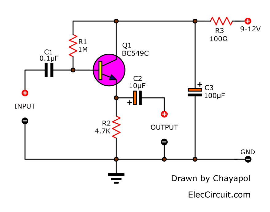
We designed it using the principle of emitter follower circuit (common collector). In this circuit design, makes the input impedance high And low impedance output.
The input impedance of this circuit is equal to the gain (hFE) of the transistor times the resistance of the emitter pin (R2).
How does the circuit work
What is an emitter follower circuit? It is a type of transistor circuit that has an input signal through the base pin (ฺ B). Then amplify the signal to get stronger and go out through the emitter pin (E).
When the bias had finished arranging for this circuit.
We feed the power supply through decoupling consisting of R3, C3 directly into the collector pin (C) of Q1, and feed the bias current to Q1 through R1 as well. Next, the output or load across from R2 which is the emitter resistor.
If the transistor used as a high gain transistor will give the input impedance of approximately 100K.
This circuit has the advantage of extending the high-frequency signal well. Less high-frequency loss. And solve the problem of hum or RF noise. When playing with record players or guitar well.
The output impedance is approximately 1,000 ohms and the output voltage is slightly higher than unity (1 time).
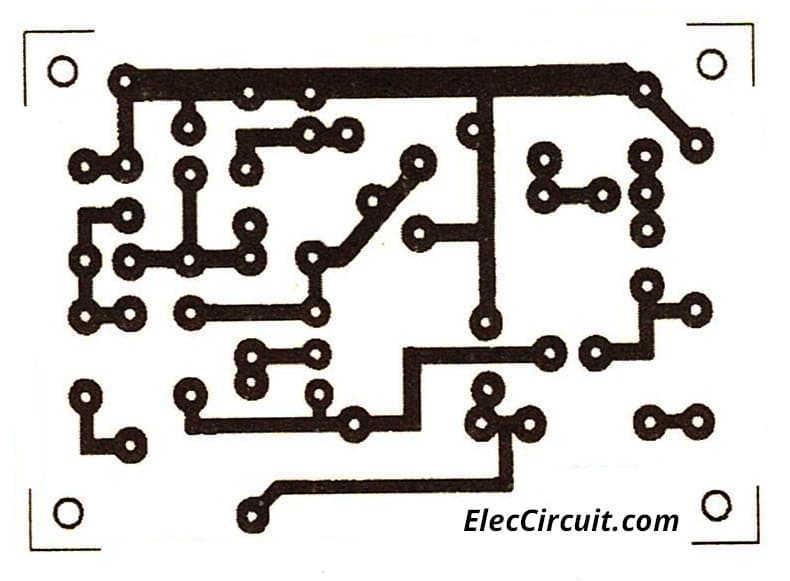
How to build
See the Actual-size of Single-sided Copper PCB layout which has the same characteristics as other Preamplifier circuits. And see the component layout.
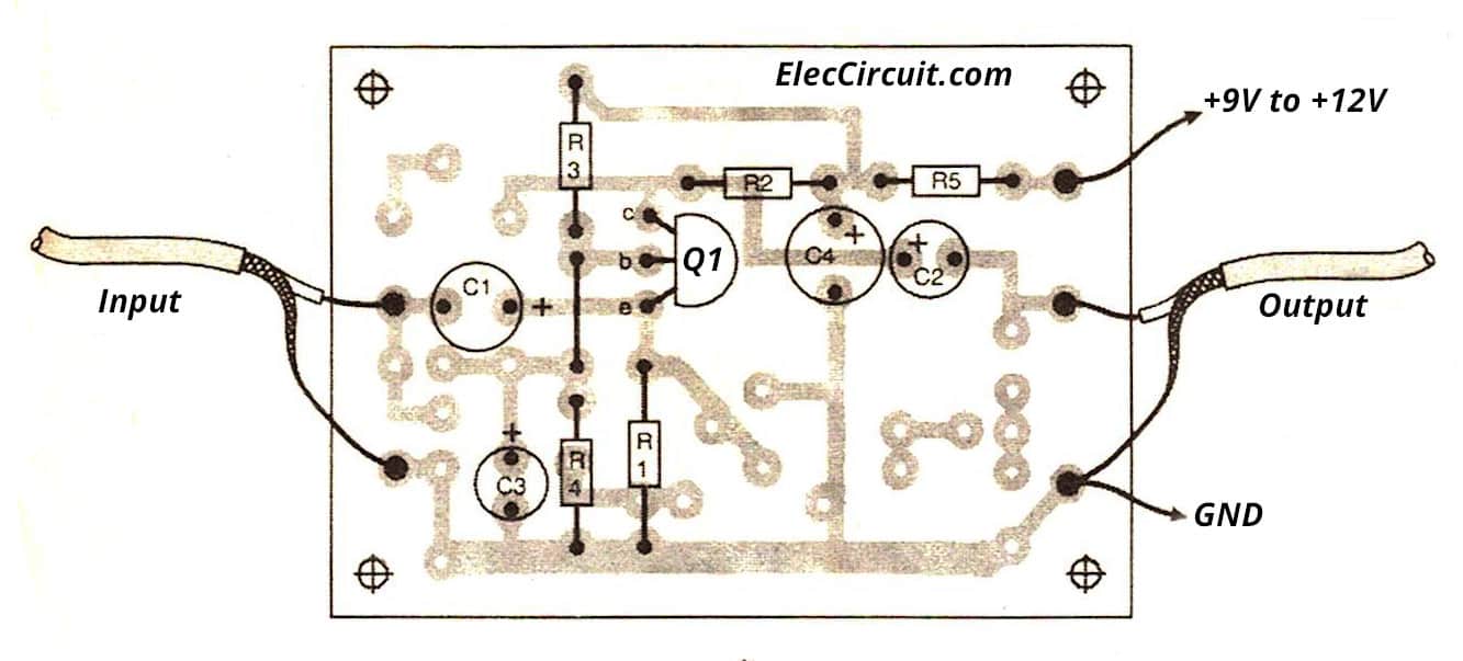
Components layout of high impedance preamplifier
Parts you will need
0.25W Resistors, tolerance: 5%
- R1: 1M
- R2: 4.7K
- R3: 100 ohms
Capacitors
- C1: 0.1uF 50V Ceramic
- C2: 10uF 25V Electrolytic
- C3: 100uF 25V Electrolytic
Semiconductors
- Q1: BC549C or equivalent, 45V 0.1A, NPN Transistor
How to increase the input impedance
If we want to increase the input impedance of the bipolar circuit even more We can do this by using the positive feedback circuit. From the emitter pin back to the base to build a network circuit for Bias.
The above method, if made easy We have to use 2 transistors, like the amplifier circuit on the tape radio. That is commonly used in the olden days.
But if you still want a high impedance preamplifier circuit that only uses one device. We have to change from transistor to FET. Read more in the article.
Not only that we see small High impedance preamplifier
Try tiny amplifier circuit
This is a high impedance small amplifier circuit. It can give power output about 1W with connecting to a 9V power supply. The advantage of this circuit is using dual Darlington transistors. So they have more size of input impedance about 20 Mega ohms.
This circuit is unlike other circuits. The input impedance is always a constant of about 20 Megohms. Whether we will adjust the volume control on any levels.
Look at the circuit below.
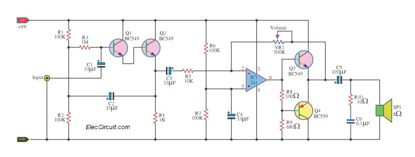
The components in the circuit, they are so cheap.
Especially the all transistors output, BC549, and BC559. So, if we increase the power. They may be very distorted. We must reduce the current level to a safe. By reducing the volume down.
The output section is the R1 and C1 in order. To reduce the oscillator gain. In fact, the output sector, including an op-amp 741 acts as a drive dual complementary.
Read more 741 0p-amp circuits
6V transistor Amplifier circuit
Generally in work learning of transistor. Also, it is a High impedance small amplifier circuit. We can divide the work period of the transistor are 3 the period.
For example, the period cut off be transistor stop work. At this period have no bass current (Ib) and collector current (lc). The period is full be intermittently at current flow through with full ahead.
Until reach the condition is full and the trend will don’t flow increase back and forth the reed that the this.
And the period active be intermittently at transistor work Bias current.
We can find a gain ratio value current. Thus in using transistor power amplifier, as a result, will very the circuit work during active.
Which we will live expansion ratio way value current of the transistor.
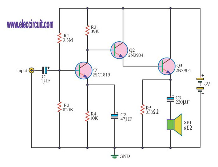
There are R1 and R2 to build a divide bias voltage. To give Q1 by having a signal output at collector pin (C). But a signal has still not enough.
Then, we must induce to amplify with Q2 and Q3 again.
Which Q2 and Q3 each other be Darlington circuit be the lead transistor 2 pcs. They have alike property comes to each other. They will get the gain rate rises.
From that time a signal that enlarged reach a loudspeaker SP1 makes a louder sound out.
Check out these related circuits, too:
- High impedance small amplifier circuits
- Video amplifier splitter circuit using transistor
- Let’s try the 3 transistors Audio Amplifier circuits
- 4 Preamplifier circuits using transistors
GET UPDATE VIA EMAIL
I always try to make Electronics Learning Easy.
Related Posts


I love electronics. I have been learning about them through creating simple electronic circuits or small projects. And now I am also having my children do the same. Nevertheless, I hope you found the experiences we shared on this site useful and fulfilling.
Hocam sen bu devreye preamplifikatör demissin ama bu devrenin gerilim kazancı sıfır olsa olsa empedans uygunlaştırıcı olur…
Hi hakan
Thanks for your sharing.
It is correct as you said.
What do you think we should call it? And how to improve it.
Please share again.