If you are a beginner that wants to build a Mini amplifier with tone control.
TDA2004/TDA2005 subwoofer Bridge Amplifier circuit diagram.
This is one of the best choices, the integrated amplifier.
With this, you can share a good sound of music from your cell phone to a big speaker.
All friends in the room will be happy with nice music.
Why should you make it?
- Can increase the sound output of 20 watts at 8 ohms speaker.
- Requires a 12V power supply so easy.
- Small circuit with one IC and more little parts.
- You can adjust the volume, bass, and treble.
- That important it is cheap, too.
How TDA2004 Amplifier works
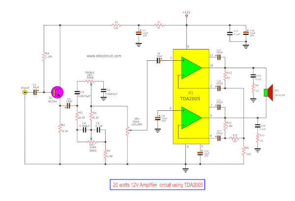
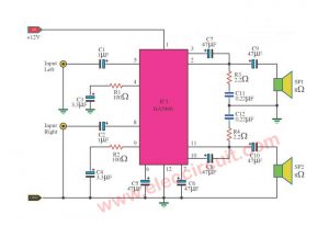
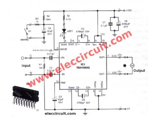
The key to this project following the circuit diagram below is TDA2005. It is a 20 watts bridge/stereo amplifier for the car radio.
Or You use TDA2004 10 + 10 W stereo amplifier as well.
The internal structure of the TDA2005 includes two op-amps. In this circuit, we connect them in bridge model.
This form, there is a lot of the output power, more than others.
If you use a mono system the output of 10 watts. But in the bridge system the output of 20-30 watts. At the same are an output speaker and a power supply.
It is a power amplifier for the car radio, so uses voltage of power supply is 12 volts 14.4 volts.
Importance, it is able to response frequency from 35 Hz to 15 KHz.
We know the feature of TDA2005 amplifier circuit diagram enough. We let to see how it works better.
Recommended: 50W-75W integrated Amplifier
To begin with, An input signal comes into this circuit through capacitor-C1. Then transistor-Q1 amplifies this signal rises up.
Which there are capacitors C2, C3, C6, and potentiometer VR2—Treble controlling—to adjusts the signal level or the high-frequency sound.
The capacitor C4, C5 and potentiometer VR3—Bass controlling—to adjust a Level of the low frequency or bass sound.
And, VR1—Volume—to adjust the size of the input signal.
After that, the capacitor C8 coupling signal to input-pin1 of IC1 to increase higher signal.
- The gain output, set with resistors R9, R10 and R12.
- Two capacitor C12 and C11 are boost trapping to low frequency.
- C17 is feedback and set the low frequency.
- C14, R8, and C18 and R13 protect a high frequency modulating oscillator.
- The output of this circuit is at pin 8 and pin 10 of IC1.
12V 2A, DC power supply circuit for TDA2005 Amplifier
We like a great sound so we need to use a proper power supply for this project.
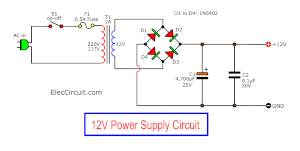
We use the 12V 2A DC power supply circuit diagram, above.
If you have a lot of hum may is ripple Read HERE
It is suitable for this. Because of an enough current, easy, cheap.
It is an unregulated power supply circuit.
Here is the step-by-step process.
- First, the transformer reduces the AC main 220VAC into down to 12VAC.
- Second, use the diodes in the bridge rectifiers to converts AC voltage to a pulsed DC.
- Third, the capacitor C1 smooth filter such DC voltage to steady DC output.
- Fourth, the capacitor C2 reduces noise caused by high frequency.
How to build a TDA2005 bridge amplifier
The parts you will need
IC1 = TDA2004 or TDA2005 (20 W bridge/stereo amplifer for car radio)
(Buy TDA2005 HERE)
Q1 = BC549—45V 100mA NPN Transistor
R1,R2,R6 = 8.2K—1/4W Resistors
R3,R11 = 1.8K—1/4W Resistors
R4 = 1.2M—1/4W Resistors
R5,R9 = 33 ohm—1/4W Resistors
R7,R12 = 1K—1/4W Resistors
R8,R13 = 1 ohm—1/4W Resistors
R10 = 10 ohm—1/4W Resistors
C1,C2,C8,C9,C10 = 10uF 25V — Electrolytic Capacitors
C7,C15 = 22uF 25V—Electrolytic Capacitors
C11,C12,C16,C17 = 100uF 25V—Electrolytic Capacitors
C5,C13,C14,C18 = 0.1uF 63V—Polyester Capacitor
C4,C6 = 0.068uF 63V—Polyester Capacitor
C3 = 0.0033uF 63V—Polyester Capacitor
VR1,VR2,VR3 = 50K (B)—Potentimeter
The heat sink, power supply 12V
Note: This circuit is mono, If you want in stereo systems, Just create another set.
We need to build PCB first. We watch the video how to make PCB: Make Your Own Printed Circuit Boards on a Laserjet!
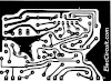
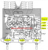
Figure 4 the components layout
We soldering electronic components onto the PCB layout.
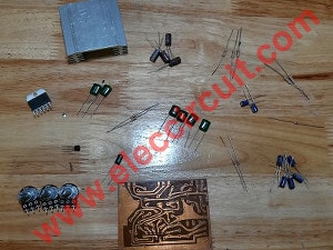
Then, prepare parts ready as the list above.
First of all, my son cleans the legs of electronic components. To can solder them easier and good.
Then, Figure 4 the components layout. We start to solder from three short wires, followed by a slower device, resistors, capacitors, transistor and important IC1.
Then, check the connector of the device as well.
Do not use the soldering iron tip to legs of devices for a long time. It may damage.
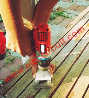
The heat sink of IC1 should be a proper size (Not too small). And screw the IC1 tightly.
We use the heat sink as Figure 5. My son drilling holes of the heat sink to install the IC1.
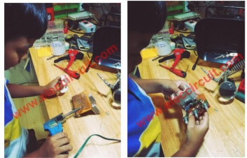
My son is building this project. It is easy for him that 9 years old. You can also make it.
Another important thing is the shield or a ground connection.
We should connect a body of metal components to the ground. For example potentiometers, the body of IC. It protects a noise signal well.
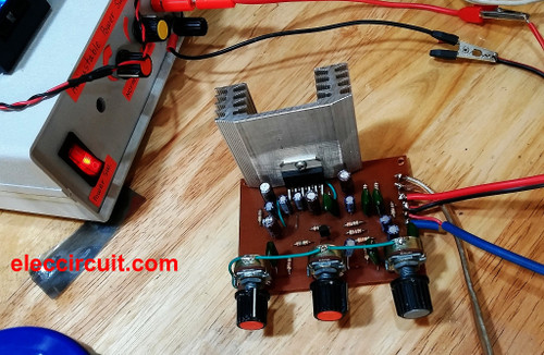
He is testing this project as a 20watt Integrated Amplifier using TDA2005.
He uses the old small speaker in 8 oms size so well sound for mini-room.
Download This!
All full-size images and PDF of this post are in this Ebook: Elec Circuit vol.1 Thanks for your support. 🙂
Related Posts

I love electronics. I have been learning about them through creating simple electronic circuits or small projects. And now I am also having my children do the same. Nevertheless, I hope you found the experiences we shared on this site useful and fulfilling.
Excellent.
can this be used as an active subwoofer?
I want the PCB for TDA2004. Being at at Chennai, Tamil Nadu India. Where can I get it?
i shall be thankful.
GVHarid
+91-9940291012
+91-00-42064508
¿Can this work with a TDA2009? Thank you.
Hai Im Rajesh I Asking A Question You Will Giving Real Circuit? This Question Asking To Clear My Dout Please Answer Me Thanking You.
Hi,godson.
Thanks for your feed back.
does it work properly
Hi,vasudev
Yes, you can do it worked sure.
Thanks your feedback.
can i use a 120 watts 8 ohms speaker on the amplifier??
Hi, macky
Thanks for your feedback.
Yes, you can.
there still noises even i followed the circuit for the power supply, what should i do about it? thank you.
Hi, If I already have a lower wall voltage power cable, there is no need for the secondary circuit correct? Just wanted to clarify. I don’t feel like working with 220 volts from the wall…
am having a 12v car battery, can i use it as power supply will it work? And What can i use in absence of transistor bc549/548
Can I use C945 for the transistor???
Hi Francis,
Thanks for your feedback.
Yes, you can but all legs difference them, be careful!
Hi ernest,
Yes, you can use 12V battery and transistor bc549/548
Hi Eric F,
Yes you can use 12V battery.
Sir it is super noisy even though i followed your circuit. Pls Help me
Hi,
Oh…I am sorry to hear that. Please check circuit again. Sometimes If we do not connect the good the ground. The circuit will have too much noise. For example: At potentiometers, a body of IC1. Please look at component layout again.
Can be used for active subwoofer , depend the power of subwoofer. A rule of thumb , because the subwoofer can have low impedance at low frequency , the amplifier must be oversized. A example is : if you have an subwoofer of 10W , then the amplifier is good to be 20W power, in literature is called damping factor. If you have this one , then is good. Also you can parallel more TDA2005 kit amplifier. Another rule of thumb , use an amplifier for every speaker, because of emf generated from each speaker, this can reduce your frequency response.
I can use as a guitar amp ?
and if so . what kind of changes would have to do.
Thank you.
I built this amp but isn’t working at all ,
would the ground wires soldered onto the potentiometers cause this cause I never did that …
..meron bang nka mirror na layout ng 20watt amplifier?
saw your 20watt integrated amp using tda2005.. can this amp be used a guitar amp.as it
is constructed . or do modifications have to be made.. if it can be used this way i will buy your ebook.
You can definitely use it as a guitar amplifier. I haven’t built this circuit yet but I was using another tda2005 circuit as a portable guitar amp. I was powering a Jensen MOD 6″ speaker and using a bank of D-cell batteries to power it at 12v. It was surprisingly loud. But it didn’t have tone controls. I added an on-off switch, an led and a second input jack (so I wouldn’t need an adapter if I was just plugging in my cell phone.).
sir is their any other way to get this ebook i mean i can pay u lke direct bank transfer or something because this paypal is not working
Looking full theory of
LED
Hi, I don’t understand the part where the input was being inserted with a signal, please if you may clarify for us what was it. It’ll really helps a lot if you respond.
Thank you !
Thank you very much master 🙂
Sir, it has sound, but so noisy. what is the possible cause of the problem? thank you
Hi, I’ve successfully created your amplifier and its working the problem is the humming sound is to loud like the fridge and also I’ve replicated your work.
Please a little help here would be so nice.
Hi. Is it possible to buy the PCB somewhere? I live in sweden by the Wayne.
Cheers Tomas
Hi,
I am sorry. Now I cannot sell PCB for you.
Thanks for your feedback.
Happy new year.
Can i use ceramic or mylar capacitors instead of polyester for 0.1,0.068 and 0.0038 uF capacitors?
Hi
Yes, you can use them.
Do i need to connect the vack of tda 2005 ic to the ground?
Hi Spuds,
I am happy you came again. You should connect the back of TDA2005 to the ground. To reduce noise or hum on the circuit.
Have a good day. Keep your iron soldering.
what diodes you use for diode bridge?
Hi,
If you build it in MONO. You can use a bridge diode at least of 2A. And Stereo is 4A.
If i want to build this project into stereo so i must use 100k potensiometer for each 3 of them?
Hi,
Yes, you can try it. It may is different.
Hi Im jikka I have a tda2004. I want to replace tda2005. It’s work?
Hi jikka,
It works the same. Hope your amplifier is nice sound.
the pcb’s photos are not good at all. I can not see . can you send it to me via e-mail ?? I need it urgently. thanks
Hello rohullah,
Thanks for your visit to my site.
You can download it in the Ebook.
Happy New year.