Build a Complex Circuit With Simpler Ones

Some of my friends are interested in building circuits to solve various problems. So, I would like to share my experience in this area, using the idea of ​​creating a large circuit from combining many smaller circuits. The resulting circuit works systemically according to conditions that we want.

Learn how to build a bigger functional circuit from smaller modular circuits. Building a practical circuit by combining many simple and easy-to-understand circuit blocks is an excellent way to learn how the circuit works and how it is constructed.

Each example below uses the process of breaking down a complex circuit into easy-to-understand circuits or blocks. All of these blocks are then later combined to create a functional circuit.

Step-by-Step Thinking Process

  1. problems, what we have, or what we are, starting from this point first.
  2. Break down your thoughts into blocks; each block is connected to one another.
  3. Replace those blocks with small circuits, and then test them separately.
  4. Lastly, combine them into a complete circuit.

Of course, while working, there will definitely be problems. If that is the case, we can go back and look at each part one by one, with the framework being the blocks that we designed.

To begin with, we should start by understanding electronic block diagrams. If you are still confused, do not be dismayed. I used to be confused; even now I am still confused sometimes. It is normal. But when we see many examples (like from below), we will start to understand.

Electronic Block Diagrams and How to Use Them

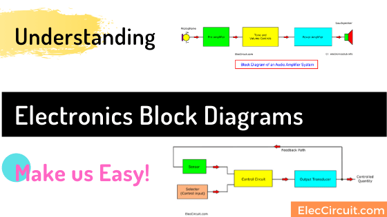
An electronic block diagram is one of the ways to represent electronic circuits. Much like a regular circuit schematic, a block diagram is used to draw or express electronic circuits, but in a simpler manner.

It breaks down a complete schematic of a circuit into multiple smaller circuits, then simplifies them into blocks. Each block represents each function of the whole circuit.

Electronics Block Diagrams

Then, we will divide them into sections or blocks. Each block has a specific function Each block is connected. Most, we will not display the components used in the block. Only the input and output are visible.

So, Looking at this makes it easy to understand or design the entire system. Almost forgot! Usually, we do not show a power source or battery in the circuit diagram.

For example electronic block diagrams

Read Back: Learning electronics for beginners with easy ways

If you cannot imagine this. Let me show you the example block diagram of many circuits.

Audio Amplifier System
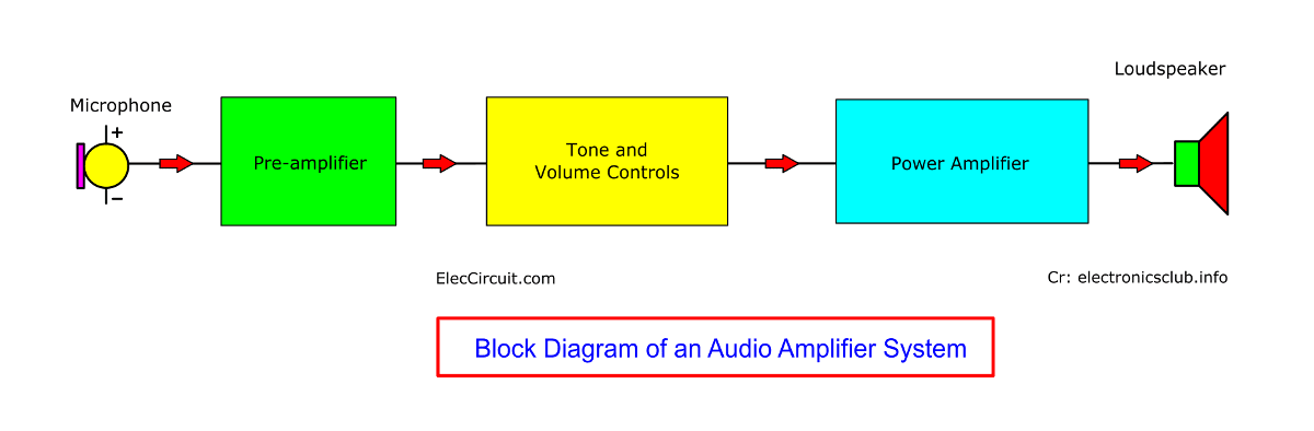
Audio Amplifier System
  • The Microphone converts sound signals into electrical signals (voltage)
  • Pre-Amplifier will increase the low level (voltage) signal from the microphone into a higher level.
  • Tone and Volume Controls
    we will adjust this to control this audio. Tone controls adjust the high frequency(Treble) and low frequency (Bass). The volume adjusts level loudness of sound.
  • Power Amplifier will increase the audio signal power up.
  • The Loudspeaker converts electrical signals to sound.

Radio Receiver System
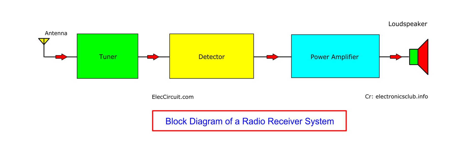
Block Diagram of Radio Receiver System
  • Antenna: serves to receive radio signals from various stations.
  • Tuner: Select only one radio station.
  • Detector: extracts the sound signal from the carrier wave that comes with the radio signal.
  • Audio Amplifier: it will amplify the audio signal to high power.
    (This part may be divided into more blocks, like the amplifier system above.)
  • Loudspeaker: converts electrical signals into sound

12V 2A Power Supply Circuit with Bridge Rectifier & Filter Design

This block diagram is quite easy, and we can use it as a broad process-by-process guideline for circuit design.

  1. Step-down transformer converts high-voltage AC mains to a lower 12VAC at the same 60Hz frequency.
  2. The diode rectifier: the 12VAC then goes into the diode rectifier, which results in a pulse DC.
  3. The filter capacitor: the pulse DC then flows through the filter capacitor, coming out as a relatively smooth 17V DC.
  4. Lastly, this DC voltage flows to the load.

Let’s learn to design DC power supply circuit with bridge rectifier and filter

Regulated Power Supply System

  • The transformer reduces the voltage from AC 220 volts to a low-voltage AC.
  • The rectifier converts AC to DC voltage. But it is DC voltage that is not smooth and has a high ripple.
  • Smoothing: filters DC power to be smooth to reduce the ripple to low.
  • Regulator: eliminate ripple signal, regulate DC output to be stable

Simple Motion Sensor Alarm Circuit Diagram

This block diagram is not too difficult, and we can use it as a broad process-by-process guideline for our circuit design. Let’s build Motion Sensor Alarm Circuit

  • The 12V Siren is an alarm-sounding device. It is easy to find, cheap, and you can choose the size (watts) you want.
  • When we use a 12V load (Siren), we should also use a 12V power supply; it should be easy to design.
  • The on-off switch block is a controller for the siren, which consumes more power than other devices in the circuit.
  • The Delay timer block is the part that extends the duration of the siren sound, even after the bear had ran away.
  • The AMP (Amplifier) block is the part that amplifies the signal from the PIR sensor to further increase the signal strength.
  • The PIR sensor is like a magic eye that keeps watching out for the bear instead of us. The new component that we have to learn.

Designing a DIY Precision Milliohmmeter Circuit

The idea for measuring the resistance is to use a constant current source and apply this constant current to the component we are testing. Then, use a voltmeter to measure the voltage across the component; the resulting voltage will reflect the resistance in a DC voltage. Read more how to design the milliohmmeter circuit in home lab.

Feedback Control System

  • Sensor: A converter that converts the controlled state into electrical signals.
  • Selector (control input): Select the desired condition of the output. Normally it is a variable resistor.
  • Control Circuit: – Compare the desired conditions from the control input and sensor of the controlled quantity and send the appropriate signal to the output transducer.
  • Output Transducer: converts electrical signals to control volume.
  • Controlled Quantity: Normally, not electric quantity, such as motor speed.
  • Feedback Path – In normal, not electric current. The sensor will detect a state of the controlled quantity.

Solar Powered Automatic Plant Watering System

This circuit consists mainly of the following components: a solar cell, a DC pump, a 555 timer, and an LM311 comparator. It worked well and was also very efficient, requiring only power from the solar cell rather than a battery. Understand this Automatic Plant Watering System works without battery!

Thank you credit source: Block Diagrams by John Hewes Learn more

How are you? Do you understand the electronics block diagrams more? I definitely want to help you. You can read more. Simple Electronic circuit examples

📘 Get Ebook: Simple Electronics VOL.5

5 thoughts on “Build a Complex Circuit With Simpler Ones”

Leave a Comment

This site uses Akismet to reduce spam. Learn how your comment data is processed.