These are three Transistor tester circuits into the Circuit or PCB. When your project does not work, the tester electronic parts or component be what need very much. Only by measuring transistor I’m tired of having to remove out one by one measuring. It wastes time and makes damage to the PCB. This circuit help make life easier. Easy to use because you do not need to remove the transistor form PCB still check it. Making we save time a lot.
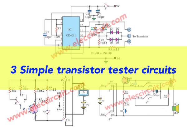
I recommend all 3 circuits as follows.
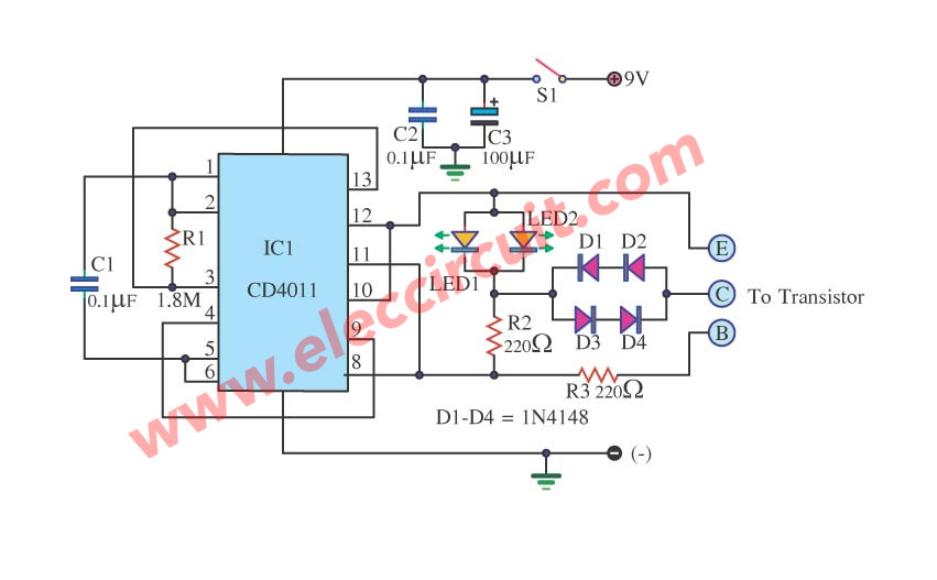
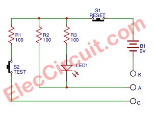
In circuit transistor tester schematic
You just know only Position legs of a transistor. then place the probe and press S1, see the led indicator good or bad of the transistor easily. It use the NAND gate digital CMOS IC-4011 series or CD4011 or MC14011 or TC4011 so useful IC very low cost. The power Supply we use battery 9volt for this circuit has low current when measuring in a circuit.
As show circuit figure above.
Learn: How do transistor circuits works
How to makes it
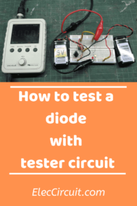
This circuit is very easy to use, so we use the perforated board, reducing the time to make this project a lot. However, you should check out the circuit carefully. To ensure the accuracy.
This circuit works you can watch video below.
Thanks
Fast transistor tester circuits
This circuit design, to determine quickly the transistors only. when not have time, or need to check the equipment.
This circuit has a simple way to work. In the test battery position (turn off switch S2). Moving coil meter 10 mA, in series with a resistance of 600 ohms(R4+R5).
When connected to a battery, 6V, so the current 10mA(moving coil current). flow meter with a needle full scale, it is available.
When the transistor was tested. S2 open, S3 is in position 2 or 3. The current will flow through the join junction base-emitter of the transistors were tested. This value can be calculated. By dividing the voltage drop across R1 or R2, with its resistance.
When S3 is in position 2 is (6V-0.6V / 560K = approximately 10 micro-amps). That is why the needle meter indicates full scale.
Which indicates that the transistor is also available.
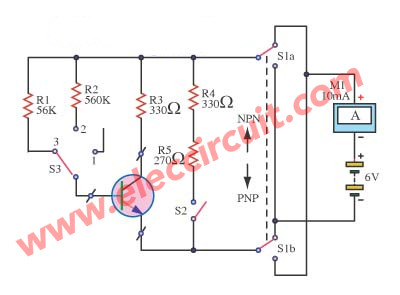
When S2 is in position 2 will be multiplied by a factor of 100. The rate of increase (hFE) of the transistor. In position 3, the resistor at the base pin will be lower than the 10 times (R1 = 56K). Therefore, the value must be multiplied by 10. For switch S1 to switch the transistor is NPN or PNP.
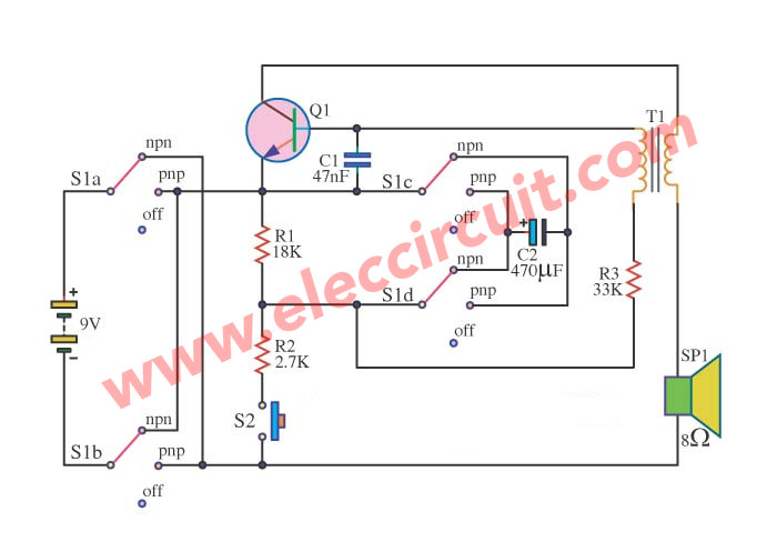
Checking Transistor with the sound
This circuit uses to check the transistor get accurately and fast. By the way, will check to tell with a sound signal.
Which, pertaining to the expansion ratio of the transistor. Then help reduce the expenses in tool expensive buying.
The transformer T1 in a picture is model output transformer at use prevents general in the receiver transistor the general.
With regard to having consuming trend low make use battery 9V get long moderately ago.
The royal utensils are model use 8ohm loudspeakers. And usability have S1 do in front on-off and choose a kind NPN and PNP of a transistor for S2 use press when want to check each time.
Friends can see the detail more in the circuit.
Quality transistor checker with buzzer
You checked the transistor by measuring the resistance between the different pins. Sometimes it has problems, such as when measuring the resistance between the various legs correctly. But it does not work in the real circuit. Because while there is no measurement bias junction between CE.
Therefore, the detection transistor good or bad for sure. the transistors must be forward. and reverse bias at the same time. Injection of the electron, or hole between the junction.
This circuit is a test. So, using the actual circuit. If the transistor test “good” circuit is the audio source it.
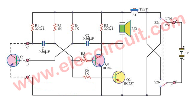
But if bad transistor. Integrated audio source will not come out. Or a very quiet voice.
This circuit of operation
To begin with, the simple astable transistors test to run during low flows about 20 mA.
Then, transistors are tested to work with Q1 to generate a frequency of about 2 KHz.
The transistors Q2 expanding output to a buzzer. The switch S2 acts during the type test transistor NPN or PNP, the switch S1 using the press to test transistors.
I love electronic circuit. I will collect a lot circuit electronic for teach my son and are useful for everyone.

I think this is a great vid. Thanks
crazy circuits and ideas. . i liked it a alot
Hi, all
Thanks for you comment.
Muito Bom Esses Teste De Transistor…
Hi,Zelino
Thanks for your feedback.
the top schematic has an error. you suppose to switch the plurality of one of the LED show that one will flash on NPN and the other will flash on PNP
Has anyone done built this circuit and got it working? I did made a proper Circuit Board, tested all connections, and once the power is switched on, one LED lit, does not matter if a Transistor is connected or not.
I did use a CD4011BE