We have many ways to indicates an AC line. First, when 230VAC is provided, the neon-lamp assemble L1 light up. Another way, the AC mains voltage indicator circuit with LED. It may be the best choice. If you have more normal components in your store. It helps you save money.
1# AC mains led indicator
I also like to use the LED for display the power AC line. Because it is cheap and convenient with a few components only.
Single LED on AC mains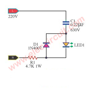
Simplest AC mains voltage indicator circuit diagram
How to connect LED to 230V AC voltage.
We know well that LED uses about 2V at 10mA only. When taking it to AC 230V. It requires reducing voltage and changing to DCV. For the first time, we often use a resistor to reduce the current in the series. But it is not suitable for the high AC voltage. Why?
The voltage across the resistor is too high, about 227V. Then, the current flows through is 10mA, like this LED. So the power of the resistor is about 227V x 0.01A = 2.27W. It is too hot.
The capacitor C1 is key in the circuit. It does not spread the heat out. (In principle)
We know that when the capacitor works in AC voltage. It is similar to a resistor. The resistance of the capacitor is called that Capacitive Reactance, in symbol Xc.
I am really stressed to explain the function of xc with simple text. I will explain to you later.
The Xc has a relationship Between frequency and capacity. If high capacity will be high Xc in the same frequency, 50Hz of AC line.
The capacitor limits the current through the LED to a safe value.
The R1 is limiting resistor to reduce the current. Also, it is the short circuit protection looks similar to a fuse.
The C1 capacitor reduces the current. It works well. When used with AC power. And rarely have problems with heat.
The diode D1 protects LED1 from the negative high voltage or current spike. Although LED1 does not work in reverse bias voltage. But this high voltage may kill its.
Important! You have to choose the capacitor-C1 Capacitors must have a DC working voltage (WVDC) of at least about 630V.
Cautions! Since this circuit no an isolated transformer, so you are careful to direct connect with into circuit. It causes electrical shock to you. AC line is very dangerous. It can kill us. Better way use the tiny isolated transformer.
I hope you are happy with this AC line 220V light display or main voltage monitor.
2# AC line indicator circuit
If you are looking for a LED display for show AC-line power. This is AC line LED indicator circuit, that is compatible with the AC main power is 115 VAC or 230 VAC. In the circuit diagram, there are 2 LEDs for showing 2 status. First, it shows AC Main or the power grid. Second, show load still hold the power or not. It is nice circuit idea because using a few parts and cheap.
Operation of circuit
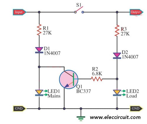
It’s a simple circuit. So interesting to learn its working. It is the main indicator of power while not pressing the switch S1. When we feed the 110V-AC to the power cord. The electrical current is flowing through R1, D1, LED1. So makes LED1 light up to reflect the input of the power.
Then, when we press switch S1, the electric current will flow through R2, D2, LED2. It makes LED2 light up instead of LED1. At the same time, some parts of the current flow to bias B lead of Q1-transistor. So, it makes Q1 work to connect all current of LED1 to ground. Makes LED1 go off.
Fuction of components
- R1,R3 limits the current through the LED1,LED2 to a safe value.
- D1,D2 rectifier AC to DC to LED1,LED2
- R2 reduce the preper current to bias Q1
What is more? Do you want to remote AC load?
Look:
3# Simple LED AC power indicator circuit
This is an LED Indicator for remote AC loads Circuit. At very cheap and use electronic parts a little. This circuit uses diode rectifier cheapness, Resistor and LED only. As a result, assemble the circuit shows flowing from AC current Source in load easily.
Although intended to design for applying to office implement with main electric, we may modify this idea goes to are usable with the level low voltage get not difficult, please.
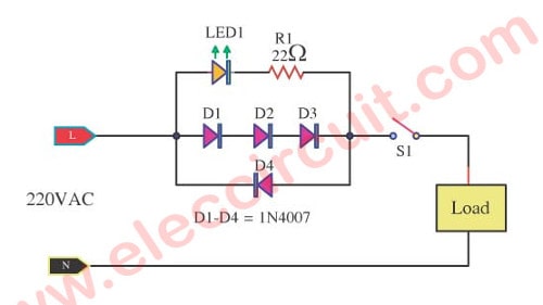
Circuit diagram of LED Indicator for Remote AC Loads
From originally at we use the way checks the condition of AC power Load by a temple AC Voltage. But when using this Simple LED AC power indicator circuit. You can check the event can work by check AC current flow through the load.
This circuit easily in case of Load and control switch stay far from the stall shows. Because misfire stands an electric line from load again the group. This circuit easily uses electronic parts a little with being normal rectifier diode 4 pcs, Resistors 1 pcs and LED 1 pcs only.
It is, as a result, can know that have current change load get already although. This circuit will suit AC house electric but this idea still can go to is using that is high-class low voltage get. By make volt be down 1.5V always just.
4# Current Transformer AC Load LED Indicator
This is a simple current transformer AC load LED Indicator circuit. The LED will show AC current of load, that use the transformer and LED as based on the circuit.
Sometimes we need to detect the large AC current. One way is to connect the LED with the resistors and the diode 1N4001 networks. But its disadvantage is the voltage will drop across them too much.
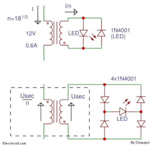
But the best way is using the current transformer. The advantage of this way is current that will check, can convert to a neat instrument. And, the transformer also helps to separate the current to be measured with a meter out.
Which are very useful in measuring high current or high voltage.
This transformer may use a normal transformer. Using the lower voltage coil connects to the high current. Then, the primary coil connects to the LED or the meter.
In choosing the transformer.
The maximum current of the secondary coil and a maximum current of the LED is determined as follows.
Example: The current detector is 0.6A. Thus the lower coil will tolerate this current size. Assuming that the maximum current for the measurement is 30 mA. So, should choose a transformer 220 volts is 12 volts. To get an accurate conversion ratio (600/30).
The voltage loss to drop across the coil of the transformer is very low. And leakage current across the coil of the transformer is very low and may abandon it.
Thus the voltage loss so as the LED voltage divided by the ratio of the transformer.
The secondary coil of the transformer has to connect to load at all times. So we have the four diodes as the bridge to show both positive and negative waveform. If no load the secondary coil will be normal coil.
GET UPDATE VIA EMAIL
I always try to make Electronics Learning Easy.
Related Posts
I love electronic circuit. I will collect a lot circuit electronic for teach my son and are useful for everyone.


One Response to “LED Indicator for remote AC loads”
Hi,
How are you friend?
I,m interesting with your LED indicator for remote AC load.can you tell me the LEd will lip up based on how many AC amp load?
I confused the LED type in your project it’s normal DC LED? Can i replace the LED with AC Bulb?
Thanks,
Could you please contact me regarding this? I’m interested in this and also a DC equivalent but with the source a max of 80VDC.
How do I power a simple indicator LED with a wide AC input range (250VAC max) and I also have another circuit with wide DC input range (80VDC max)?
Chris the voltage drop across the LED is minuscule compared to the high voltages. Subtract 2(red and yellow LED’s are normally 2 volts) or 3 volts from the AC voltage and use V = IR to use about 4 ma. That’s a 33K resistor on 120 volts and 68K on 240.
In the last circuit example, why are you rectifying 120 or 240 volts and sending it to the Load? Who needs that much DC voltage?
PS: That’s with 1/2 watt resistors. More milliamps means more watts. 8 ma(.008 amps) would require one watt resistors.
Mains indicator with LED
Thanks for your circuit!!
It works perfectly.
Just read on another web page for a 220V AC LED cct .. have the LED and a reverse connected IN4003
and instead on nay resistor just use a 0.22uF Ceramic capacitor.
Have you tried this ?
States it avoids problem of dissipating heat in a resistor.
Take a look at:
https://www.instructables.com/id/LED-on-AC-Mains/
Been looking a bit more into this … In your diag you show the 4k7 1W resistor.
You can simply leave that out … the capacitor is providing current limit.
You mention resistor is there for current limit in the event of a short.
A short where ? in capacitor ? if that is case LED would act as fuse.
Have you calculated what current is flowing thru resistor in normal state ? ……..
I am thinking of simply discarding that resistor ..
1 have added 60 led in one circuit please tell me how to connect with direct ac 210v to 240v plzz help me
i want to fix in my aquarium….
thanks
for the Mains Voltage Indicator with a LED,can i use 2000V 223nF capacitor?
Question for “Mains Voltage Indicator with a LED”. I wanted to add it in our refrigerator plug. We only power off our refrigerator at least once a month for 30 minutes.
1.) Will the circuit conneceted to our refrigerator will actually survive for at least 1 year?
2.) In C1 what is current depression
Question for “Mains Voltage Indicator with a LED”. I wanted to add it in our refrigerator plug. We only power off our refrigerator at least once a month for 30 minutes.
1.) Will the circuit conneceted to our refrigerator will actually survive for at least 1 year?
2.) In C1 what is current depression in easy-to-understand explanation? Is that the only purpose in this circuit?
3.) If circuit is connected directly to welding machine power plug (also as power indicator) will it survive for a whole day welding-heavy-usage used?
Thank You,
mia
very helpfull hobbyist and students.
Hi,
Thanks for your feedback.
How can do for three phase supply. Can it located close to the national grid meter. Can switch be included
To elucidate my question further. From the mains there are three lines. Sometimes one or two of the phases may not have electric supply and there may be a need to change to the line that has electric supply. How can I have 3 indicator lights close to the meter to help me identify the line with electricity and connect. I am afraid of shorting the three phases
Thanks, pls I need response to my earlier requests
Hi to all
I need led bulb ckt from 230v to DC ckt nd it should be 10w with 45 to 50 LEDs nd max lighting required with IC Configuration. Kindly provided this information
thanking you
satykishore
Dear Friends,
I have a 3 led power indicators to indicate the 3 phases in my cabinets, i want to know how many AMPERE for the fuse what i need.
Thanks
Capacitor supplies Suppression???
I know I am not the only one wondering.
Also the warning about polarity of connections seems a bit odd.
I’d like to know the failure mode so that I can gauge the safety of this circuit.
In short with this sort of post, when legitimate questions remain unanswered, I’d recommend getting a professional opinion before proceding.
Dear all, how many of you still do live???
Because I read a lot of inexperienced questions,
so I can imagine none of you know actually how dangerous is
life mains voltages, single or tri-phase !!!!!
A capacitor reacts as a frequency dependant resistor,
in theory without heat dissipation: Xc=1/(2*pi*f*C).
Ad if you don’t know how to use this formola,
I’d rather advice stay of it, and do something safer,
because you don’t know the heck what U’re doing.
Hello Harry,
Thanks for helping teach us. Your comment is so good. AC line is very dangerous. It can kill us. Better way use the tiny isolated transformer.
The voltage from “Line” to “Neutral” should be 120vac. Your calculations will now be different.
Hi Can you help me ? I have built the 230V LED indicator circuit detailed above. Initially it always works but once I’ve flicked the 230V switch a few times the LED stops working, Ive got the components correctly orientated so whats the problem and how do I solve it? Thanks
Greetings;
Thank you for all your great tutorials. I, an I’m sure many others find them quite useful.
I just used your “2# AC line indicator circuit” on this page in a Hot-Wire Foam Cutting Project, using one of these circuits in each handle… as in my industry we find ourselves occasionally cutting 20 foot long pieces of styrofoam with a person at each end with a handle. So as you can imagine, it is beneficial to have indicators to let the person not in control of the Variac powering the wire know that the handle now has power, and the wire is “safe” or “hot”. This works flawlessly!
I would like to add an additional LED on each circuit to show that the Hot-Wire has continuity – that it is well attached to the terminals and there are no breaks. How would I do this using the current already powering the pre-switch LED without heating the NiChrome wire and without blowing everything up once I throw the switch and want the wire hot?
Attached is a schema of the circuit. I indicated the 22 awg NiChrome wire on the plan using an Air Core Inductor symbol, which is obviously not the case. The whole thing is powered using a 20 amp Variac pushing 30 volts +/- for shorter lines to the full 110 volts on occasion for longer projects.
Thank you for your assistance!
I can’t seem to get the schema to attach to the post. Please provide an email address and I will send it.
Wow Thanks for this posting i find it hard to search for really good related information out there when it comes to this subject material thank for the review site